33. AGX Sensor
The AGX Sensor module is used to simulate accurate real time sensors that allow detection of objects and changes connected to the physics simulation.
To simulate sensors, an agxSensor::Environment will be used as a separate analogue to agxSDK::Simulation, to house references to all objects and features detectable by sensors, and the sensors themselves.
Currently, the AGX Sensor module supports the following sensor types:
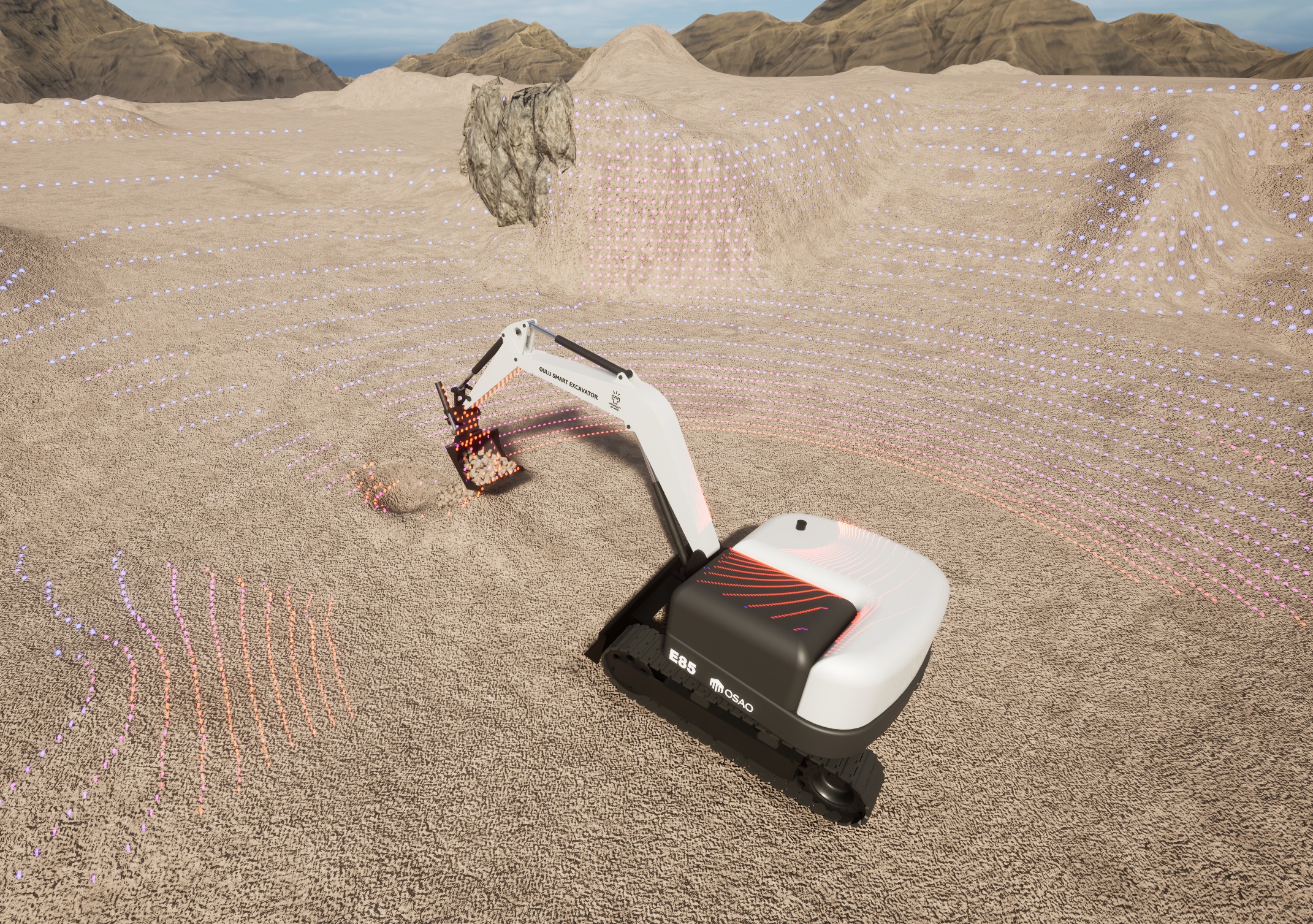
Fig. 33.1 Lidar attached to an excavator.
33.1. Environment
agxSensor::Environment primarily contains references to all objects that should be detectable by a sensor.
It is associated with an agxSDK::Simulation and any object’s movement in the agxSDK::Simulation will automatically be reflected in the agxSensor::Environment.
To create an agxSensor::Environment for a specific agxSDK::Simulation, the procedure is as follows:
agxSensor::EnvironmentRef environment = agxSensor::Environment::getOrCreate( simulation );
Where simulation is an instance of an agxSDK::Simulation.
For an object to be detectable by a sensor, it must be added to the agxSensor::Environment instance:
// Create a Rigid Body with a Box Geometry.
agxCollide::GeometryRef geometry = new agxCollide::Geometry( new agxCollide::Box( 1000, 1000, 1 ) );
agx::RigidBodyRef body = new agx::RigidBody( geometry );

// Add the Rigid Body to the agxSDK::Simulation.
simulation->add( body );

// Add the Rigid Body to the agxSensor::Environment.
environment->add( body );
The position and orientation of the Rigid Body will automatically be updated in the agxSensor::Environment as it is moved by the physics simulation handled by the agxSDK::Simulation.
Currently, the following types are supported and can be added to the agxSensor::Environment:
agx::Physics::GranularBodySystemagx::RigidBodyagxCollide::ShapeagxCollide::GeometryagxSDK::LinkedStructureagxCable::CableagxModel::BeamagxVehicle::Track
agxTerrain::TerrainagxTerrain::TerrainPageragxWire::Wire
Apart from adding objects to the agxSensor::Environment, any active sensor must also be added to it.
How to create and configure an agxSensor::Lidar sensor is described in more detail later in the section about Lidar.
33.1.1. Surface Material
Surfaces in the real world reflect light at different intensities in different directions depending on the underlying material of the object and the characteristics of the object’s surface.
AGX Sensor allows modeling of a wide range of commonly occurring surfaces using surface materials derived from agxSensor::RtSurfaceMaterial.
The various agxSensor::RtSurfaceMaterial types model the compound reflection characteristics of a surface, taking into account both the reflectivity of the underlying material and the microscopic features of the surface.
Physically, the surface materials supplied as the various agxSensor::RtSurfaceMaterial types specify the Bidirectional Reflectance Distribution Function (BRDF), \(f(\hat{l}, \hat{v})\) from the reflectance equation:
Which describes the light \(L(\hat{v})\) reflected on the surface in the solid angle \(\Omega\), from incident light \(L_i(\hat{l})\).
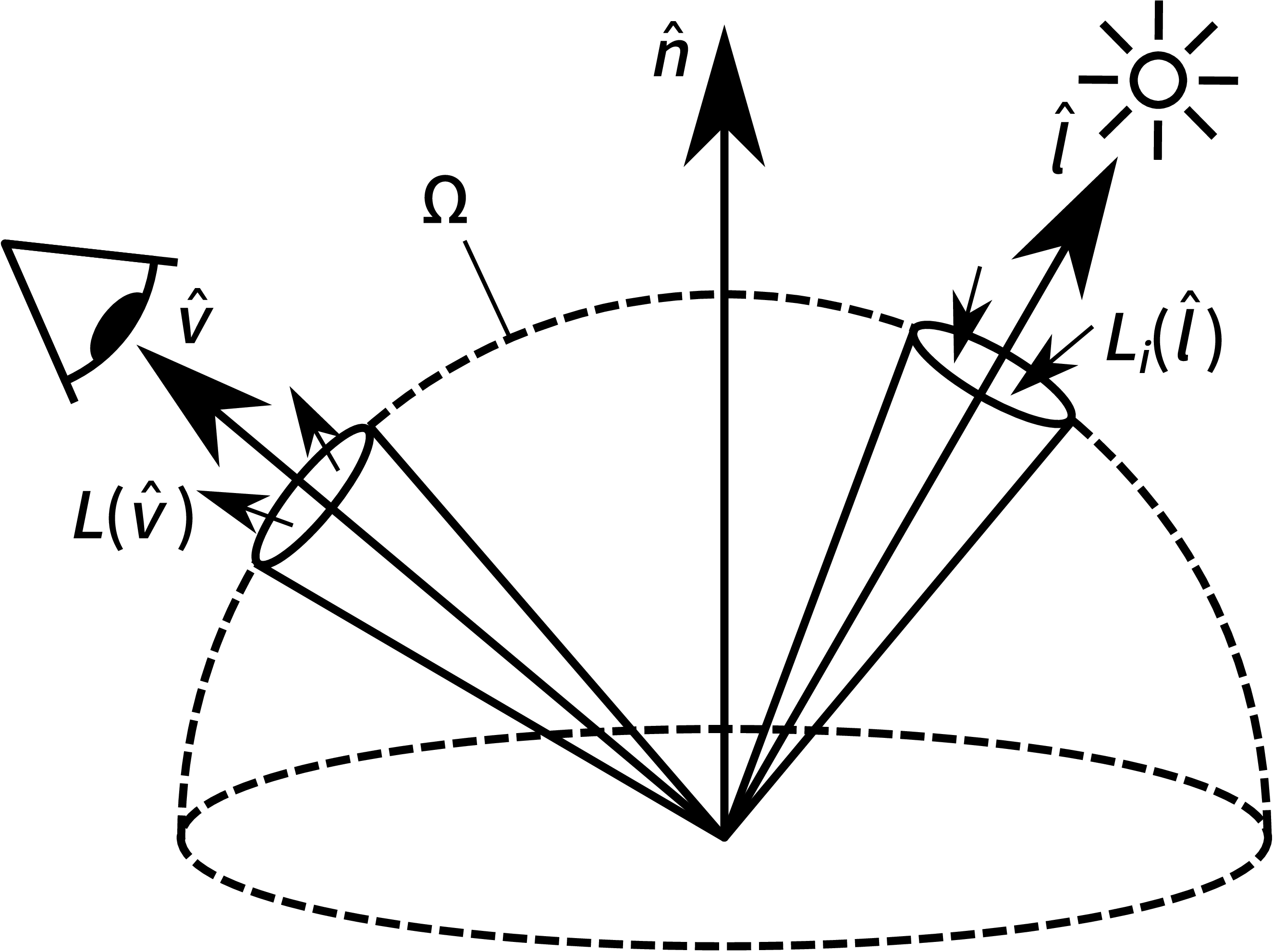
Fig. 33.2 Configuration of the reflectance equation.
Currently, AGX Sensor implements the following surface materials:
Material |
Model |
Parameter Count |
Usage |
|
Lambertian Diffuse |
1 |
Most non-specular surfaces, especially matte diffuse surfaces. |
|
GG-X and Oren-Nayar |
5 |
Specular surfaces, rough diffuse surfaces or diffuse surfaces with a specular top-coat. |
|
Explicit BRDF |
(samples) |
Advanced fallback for opaque surfaces where the other models will not suffice. |
33.1.1.1. Opaque Lambert Surface
The simplest of the agxSensor::RtSurfaceMaterial types comes on the form of the agxSensor::RtLambertianOpaqueMaterial.
This material describes a simple matte diffuse Lambertian surface, with the BRDF as:
For some total diffuse reflectivity parameter of \(C_D\). This surface material should generally be sufficient to achieve a good result for most non-specular, that is not mirror-like, surfaces, and is the default material applied to all surfaces with \(C_D = 0.8\) if no other material is specified.
To add an agxSensor::RtLambertianOpaqueMaterial, with a reflectivity of \(C_D = 0.2\), to an object in the sensor environment, the procedure is as following:
// Create the Lambertian material
agxSensor::RtLambertianOpaqueMaterialRef material = agxSensor::RtLambertianOpaqueMaterial::create();

// Set the reflectivity
material->setReflectivity( 0.2f );

// Assign the material to the object
material->assignTo( object );
33.1.1.2. GG-X and Oren-Nayar Surface
For more complex surfaces the two-layer material agxSensor::RtGgxAndOrenNayarMaterial can be used.
This material describes a surface with a GG-X microfacet specular top-layer and a secondary Oren-Nayar rough diffuse layer.
The GG-X specular layer contributes to the BRDF according to:
Where \(R_\text{Fresnel}\) is the Fresnel reflectance, \(G_\text{Smith}\) is Smith’s G-function and \(D_\text{GG-X}\) is the GG-X microfacet distribution function. Meanwhile, the Oren-Nayar diffuse layer contributes to the total BRDF according to:
Where \(A_\text{Oren-Nayar}\), \(B_\text{Oren-Nayar}\), \(s_\text{Oren-Nayar}\) and \(t_\text{Oren-Nayar}\) are the various sub-sections of the Oren-Nayar diffuse model.
As this surface material is significantly more complex than the Lambertian diffuse material, see Opaque Lambert Surface, the parameter count is likewise greater. The parameters for the agxSensor::RtGgxAndOrenNayarMaterial are as following:
Parameter |
Method |
Description |
Default |
\(n\) |
|
Real component of the specular top-layer refractive index. |
1.4517 |
\(k\) |
|
Imaginary component of the specular top-layer refractive index. This value is related to absorption of light at the top-layer. |
0.0 |
\(\sigma_\text{Beckman}\) |
|
Roughness value of the specular top-layer. This value represents the root-mean-square slope of the specular top-layer microfacets. |
0.3 |
\(\sigma_\text{Oren-Nayar}\) |
|
Roughness value of the diffuse secondary layer. This value represents the standard deviation of the normal vectors of the diffuse layer microfacets. |
0.3 |
\(C_D\) |
|
Reflectivity of the diffuse secondary layer. |
0.8 |
To add an agxSensor::RtGgxAndOrenNayarMaterial to an object in the sensor environment, the procedure is as following:
// Create the GG-X and Oren-Nayar material
agxSensor::RtGgxAndOrenNayarMaterial material = agxSensor::RtGgxAndOrenNayarMaterial::create();

// Set the material parameters (Silver mirror)
material->setRefractiveIndexReal( 0.037f )
         .setRefractiveIndexImaginary( 5.57f )
         .setBeckmanRoughness( 0.001f )
         .setOrenNayarRoughness( 0.0f )
         .setDiffuseReflectivity( 0.02f );

// Assign the material to the object
material->assignTo( object );
33.1.1.3. Explicit BRDF Surface
If neither of the other surface materials would suffice, the BRDF can also be explicitly specified using agxSensor::RtBrdfExplicitMaterial.
This material simply accepts BRDF samples on the form of a four dimensional array, flattened in memory, where the indices specify:
Sample index in \(\theta\) (vertical) direction for the light incidence direction.
Sample index in \(\phi\) (horizontal) direction for the light incidence direction.
Sample index in \(\theta\) (vertical) direction for the view direction.
Sample index in \(\phi\) (horizontal) direction for the view direction
The supplied samples should represent a non-isotropic BRDF, thus specifying the full \(\phi\) range from \(0\) to \(2\pi\). \(\theta\) ranges from \(0\) to \(\frac{\pi}{2}\). BRDF samples are suitably attained from measurement data.
33.1.2. Ambient Material
The medium through which the light travels to, or from, a sensor may contain disturbances which can affect the measured data.
AGX Sensor supplies a simple way to model homogeneous atmospheric disturbances through agxSensor::RtAmbientMaterial.
The agxSensor::RtAmbientMaterial has a number of parameters which control the behavior of light signals in the medium:
Parameter |
Method |
Description |
Default |
\(n\) |
|
Ambient material refractive index. |
1.000273 |
\(\alpha\) |
|
Signal attenuation coefficient. |
0.000402272 m-1 |
\(A\) |
|
Atmospheric return gamma-distribution scaling. |
1.58899 * 10-5 |
\(k\) |
|
Atmospheric return gamma-distribution shape parameter. |
9.5 |
\(\theta\) |
|
Atmospheric return gamma-distribution scale parameter. |
0.52 m |
The refractive index \(n\) and attenuation coefficient \(\alpha\) describe the general propagation speed and attenuation of the signal. Meanwhile, the \(A\), \(k\) and \(\theta\) parameters describe the probability at, and location where, the signal may spontaneously reflect in the medium.
To simplify the configuration of ambient materials, agxSensor::RtAmbientMaterial also specifies a number of helper methods for common weather phenomena:
Method |
Description |
|
Configures the |
|
Configures the |
|
Configures the |
|
Configures the |
An agxSensor::RtAmbientMaterial, configured for continental fog of 2.0 km visibility, is added to the sensor environment through the following procedure:
// Create the ambient material
agxSensor::RtAmbientMaterialRef material = agxSensor::RtAmbientMaterial::create();

// Configure as fog for a 905 nm signal
material->configureAsFog( 2.0f, 905.0f );

// Add to sensor environment
environment->getScene()->setMaterial( material );
33.1.3. Magnetic Field
For magnetometers to work properly, the agxSensor::Environment has a magnetic field specified that spans the Environment. This magnetic field is per default set as an agxSensor::UniformMagneticField instance, see Uniform Magnetic Field, with its uniform magnetic field vector mimicking one that could be found on the surface of the Earth. To change the Environment’s magnetic field from the default, the magnetic field is simply set for the Environment as:
// Configure the magnetic field in the environment
environment->setMagneticField( magneticField );
Where environment is an instance of an agxSensor::Environment and magneticField is an instance of a type derived from agxSensor::MagneticField. To specify the magneticField instance, one either use one of the pre-defined magnetic field types, or create one’s own type inheriting from agxSensor::MagneticField.
33.1.3.1. Uniform Magnetic Field
An agxSensor::UniformMagneticField instance defines a simple magnetic field that is uniform across the entire sensor Environment, and suitable for fairly local navigation. This magnetic field instance is created by specifying a magnetic field vector that will be used across the entire Environment:
// Find a suitable magnetic field vector (in tesla)
agx::Vec3 magneticFieldVector{ -19.462e-6, 44.754e-6, 7.8426e-6 };

// Create a uniform magnetic field
agxSensor::UniformMagneticFieldRef magneticField =
  new agxSensor::UniformMagneticField( magneticFieldVector );

// Configure the magnetic field in the environment
environment->setMagneticField( magneticField );
33.1.3.2. Dipole Magnetic Field
For longer range navigation it may sometimes be viable to use a dipole approximation of the Earth’s magnetic field, using an instance of agxSensor::DipoleMagneticField. This magnetic field instance is created by specifying a magnetic moment vector and the center position of the dipole in world coordinates:
// Find a suitable magnetic moment vector (in m²A)
agx::Vec3 magneticMoment{ 2.69e19, -7.65e22, 1.5e22 };

// Find a suitable center for the dipole
agx::Vec3 dipoleCenter{ -1.9e-10, 20.79e3, -6.369e6 };

// Create a dipole magnetic field
agxSensor::DipoleMagneticFieldRef magneticField =
  new agxSensor::DipoleMagneticField( magneticMoment, dipoleCenter );

// Configure the magnetic field in the environment
environment->setMagneticField( magneticField );
33.1.4. Different Rate Stepping
In certain cases, such as when running the dynamics simulation at a very high step rate, it may be useful to run certain sensors at a different, lower, step rate.
This may be especially useful for sensors that rely on synchronization between the CPU and GPU, such as the Lidar.
One way to achieve this is by adding the sensors to an agxSensor::SensorGroupStepStride, which steps the sensors at a lower rate compared to the agxSensor::Environment as specified by a stride value:
// How many environment steps per sensor step?
agx::UInt32 stride = 5u;

// Create the group
agxSensor::SensorGroupStepStrideRef group = new agxSensor::SensorGroupStepStride( stride );

// Add the sensor to the environment through the group
group->add( sensor );
environment->add( group );
Any sensor added to an agxSensor::SensorGroupStepStride will produce output at the lower step rate of the group, and thus not at the full environment step rate.
33.2. Lidar
Fig. 33.3 Lidar attached to an excavator.
agxSensor::Lidar is a sensor type in the AGX Sensor module.
It uses GPU accelerated ray tracing to enable accurate real time simulation of Lidar and provides a means to access the generated point cloud data.
In order to be active and able to detect objects within an environment, the Lidar must be added to the agxSensor::Environment:
agxSensor::LidarRef lidar = new agxSensor::Lidar( frame, model );
environment->add( lidar );
Where environment is an instance of an agxSensor::Environment, frame is an optional agx::Frame and model is an agxSensor::LidarModel.
The frame parameter can be set to, for example, attach the Lidar to anything moving in the simulation, such as a Rigid Body.
Meanwhile, the model determines the behavior and characteristics of the Lidar.
Specifying which output a Lidar should produce, and later accessing the resulting point cloud data, is done using the agxSensor::RtOutputHandler, see Output Handler for details.
An example of how to set up a Lidar simulation scenario in Python can be found in Algoryx/AGX-version/data/python/tutorial_lidar.agxPy.
A C++ tutorial can be found in Algoryx/AGX-version/tutorials/tutorial_lidar.cpp.
33.2.1. Lidar Model
An agxSensor::LidarModel is what determines the behavior and characteristics of an agxSensor::Lidar.
A number of built in Lidar Models are available, below is an example of how to use the built-in agxSensor::LidarModelOusterOS1 to create a horizontally sweeping Lidar mimicking the Ouster OS1 Lidar:
agxSensor::LidarModelRef model = new agxSensor::LidarModelOusterOS1();
agxSensor::LidarRef lidar = new agxSensor::Lidar( frame, model );
environment->add( lidar) ;
Where environment is an instance of an agxSensor::Environment and frame is an optional agx::Frame, which can be set to, for example, attach the Lidar to anything moving in the simulation, such as a Rigid Body.
It is also possible to create custom Lidar Models where, for example, a custom ray pattern can be implemented:
agxSensor::LidarModelRef model = new agxSensor::LidarModel( myCustomRayPatternGenerator,
                                                            agx::RangeReal32{ 0.5, 30.0 },
                                                            lidarProperties,
                                                            lidarOutputNoises );
Where myCustomRayPatternGenerator is an implementation of Ray Pattern Generator, which configures when and in which direction the Lidar sensor will emit its rays, lidarProperties is an optional parameter specifying additional properties of the Lidar and lidarOutputNoises is an optional agxSensor::RtOutputNoiseRefVector which can be used to define distortions applied to the Lidar output on a per-model basis.
For more details about the Ray Pattern Generator, see Ray Pattern Generator.
33.2.2. Predefined Lidar Models
33.2.2.1. Ouster
A number of predefined Lidar models based on popular Lidar sensors are included with the AGX Sensor module, each with their own set of hardware configurations and software settings.
Ouster OS0 - Ultra-Wide View High-Resolution Imaging Lidar
Ouster OS1 - Mid-Range High-Resolution Imaging Lidar
Ouster OS2 - Long-Range High-Resolution Imaging Lidar
The OSx series currently have the following predefined configuration options:
Hardware configuration of 32, 64 or 128 channels
Beam spacing options uniform, above horizon and below horizon
Configurable frequency / horizontal resolution settings 512x10, 512x20, 1024x10, 1024x20, 2048x10
33.2.2.2. Livox
The Livox lidar models included with the AGX Sensor module are simulated using a repeating but large set of ray angles, coming close to the non-repeating pattern displayed by the Livox hardware lidars. The only configuration option available is the Downsample option, which skips ray angles in the pattern in order to get the same shape but less points per second. The list of available models are:
Livox Avia - Mid-range 70 by 77 degree fov lidar with non-repeating pattern.
Livox HAP - Mid-range 120 by 25 degree fov lidar with non-repeating pattern for automotive applications.
Livox Horizon - Mid-to-long-range 82 by 25 degree fov lidar with non-repeating pattern.
Livox Mid40 - Short-to-mid-range circular 38 degree fov lidar with non-repeating pattern.
Livox Mid70 - Short-to-mid-range circular 70 degree fov lidar with non-repeating pattern.
Livox Mid360 - Short range 360 by 59 degree fov lidar with non-repeating pattern.
Livox Tele - Long range 14 by 16 degree fov lidar with non-repeating pattern.
The ray pattern files are sampled from the Livox Sensor SDK and then included with this package compressed to binary. The ray pattern files are released by Livox under MIT license. These same files are under the same license in this module.
33.2.3. Ray Pattern Generator
The agxSensor::LidarRayPatternGenerator is responsible for generating the ray pattern used by the Lidar.
Either, one of the built-in Ray Pattern Generators such as agxSensor::LidarRayPatternHorizontalSweep can be used, or a custom Ray Pattern Generator can be implemented by the user.
The ray pattern is represented by an array of transforms stored within the Ray Pattern Generator. For each simulation step, an interval within this array is chosen to be active during that simulation step. This way, the whole ray pattern can be set once, and parts of the ray pattern can then be activated each simulation step in an efficient manner.
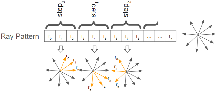
Fig. 33.4 Different parts of a ray pattern is active during different simulation steps.
The order of the rays stored in the agxSensor::LidarRayPatternGenerator determines the order of the output data once it is read via the Output Handler.
Each ray is cast from the position determined by the stored transform origin and is cast along its z axis.
The ray transforms are relative to the transform of the Lidar.
Each simulation step, during PRE_STEP, see Step Events, getNextInterval() in the agxSensor::LidarRayPatternGenerator instance will be called, and it is the responsibility of the Ray Pattern Generator to return an interval within the stored ray pattern array.
The ray pattern array is set by calling setRayTransforms() in the agxSensor::LidarRayPatternGenerator instance.
The ray pattern array can be set once, for example in the constructor of any Ray Pattern Generator, or it can be set more frequently, for example each time getNextInterval() is called.
This is up to the implementation of the Ray Pattern Generator to decide, as long as the interval returned by getNextInterval() is within the currently set ray pattern array.
By setting the ray pattern array only once, performance can be improved.
33.2.4. Ray Distortion Handler
The agxSensor::LidarRayDistortionHandler of a Lidar can be used to add distortions to the Lidar rays before they are emitted from the sensor.
33.2.4.1. Angle Gaussian Noise
An agxSensor::LidarRayAngleGaussianNoise instance can be added to the Lidar’s distortion handler to apply Gaussian noise to the emission angles of the Lidar rays:
// Create a ray angle noise with 0.02 radians standard deviation
agxSensor::LidarRayAngleGaussianNoiseRef noise = new agxSensor::LidarRayAngleGaussianNoise();
noise.setStandardDeviation( 0.02f );

// Set perturbation vector to X (vertical noise)
noise.setAxis( agxSensor::LidarRayAngleGaussianNoise::Axis::AXIS_X );

// Add noise to the Lidar
lidar->getRayDistortionHandler()->add( noise) ;
The noise added to the ray angles through agxSensor::LidarRayAngleGaussianNoise will alter the angle of the Lidar rays without compensating the output, and thus the angle perturbations will be visible in the resulting Lidar output.
33.2.5. Output Handler
The agxSensor::RtOutputHandler of a Lidar is used to define what data will be generated during ray tracing.
It also provides a convenient way of accessing this data.
The Output Handler can be accessed by calling:
lidar->getOutputHandler();
where lidar is an instance of agxSensor::Lidar.
The output of a Lidar is defined using one or several fields defined in agxSensor::RtOutput::Field.
The field XYZ_VEC3_F32 is used when the (local) locations of points are of interest, INTENSITY_F32 is used when intensity should be included etc.
These fields can be combined in any order to configure the output of the Lidar.
The type of the output is given by the user, and it must have memory alignment matching the fields used to define the output.
Below is a minimal example of this, for a more detailed example, see the example and tutorial listed in Lidar:
lidar->getOutputHandler()->add<MyStructType, RtOutput::XYZ_VEC3_F32, RtOutput::INTENSITY_F32>();
Here, MyStructType must have a memory layout of four float contiguous in memory.
Three float members where the x, y and z will be written to and a fourth float member to which the intensity will be written.
It could for example also have been of type agx::Vec4f, or any other type fulfilling this requirement.
Accessing the output data of a Lidar can also be done using the Output Handler.
This should be done in each POST_STEP of the agxSDK::Simulation time step.
Below is a minimal example of this, for a more detailed example, see the example and tutorial listed in Lidar:
auto view = lidar->getOutputHandler()->view<MyStructType>();
for ( const auto& p : view )
  // Access p which is the MyStructType data (point) for this ray.
Note that calling view is blocking, i.e. it waits until the Lidar output is available, which is generated on the GPU.
33.2.5.1. Distance Gaussian Noise
Gaussian noise can be added to the distance, from the sensor, at which the points in Lidar data will appear by adding an agxSensor::RtDistanceGaussianNoise instance to the Lidar’s output handler:
// Create a distance noise with a base standard deviation of 0.005 m...
agxSensor::RtDistanceGaussianNoiseRef noise = new agxSensor::RtDistanceGaussianNoise();
noise->setStdDevBase( 0.005f );

// ...growing with 0.001 m/m
noise->setStdDevSlope( 0.001f );

// Add noise to the Lidar output
lidar->getOutputHandler()->add( noise );
33.2.5.2. Sending output over ROS2
It is possible to use ROS2 to publish point cloud data from lidar sensors via the functions available in the agxROS2 module. For more details see ROS2 and PointCloud2 usage with agxSensor.
33.3. Inertial Measurement Unit
Inertial Measurement Units (IMUs) can appear in multiple different configurations, both of sub-sensors and output formatting, depending on manufacturer and requirement specifications.
agxSensor::IMU in the AGX Sensor module provides a way to model most standard IMUs, and provides a standardized way to collect signals from the IMU’s sub-sensors, providing the readings through the common IMU interface.
An agxSensor::IMU is attached to a frame, and in order to be active, it must be added to the agxSensor::Environment:
agxSensor::IMURef imu = new agxSensor::IMU( frame, model );
environment->add( imu );
Where environment is an instance of an agxSensor::Environment, frame is an optional agx::Frame and model is an agxSensor::IMUModel.
The frame parameter can be set to, for example, attach the IMU to anything moving in the simulation, such as a Rigid Body.
Meanwhile, the model determines the behavior and characteristics of the IMU.
Specifying which output an IMU should produce, and later accessing the resulting signal, is done using the IMU’s agxSensor::IMUOutputHandler, see Output Handler for details.
33.3.1. IMU Model
An agxSensor::IMUModel is what determines the basic characteristics of an agxSensor::IMU.
It is the agxSensor::IMUModel which is used to specify which sub-sensors are attached on the IMU, and in which order they are accessed when assembling the output signal.
Currently, an agxSensor::IMUModel can hold attachments for the following sensors:
Accelerometer, through an
agxSensor::IMUModelAccelerometerAttachmentGyroscope, through an
agxSensor::IMUModelGyroscopeAttachmentMagnetometer, through an
agxSensor::IMUModelMagnetometerAttachment
When constructing an agxSensor::IMUModel, the attachments are supplied through an agxSensor::IMUModelSensorAttachmentRefVector:
// Specify a model attachment vector
agxSensor::IMUModelSensorAttachmentRefVector attachments{
  new agxSensor::IMUModelAccelerometerAttachment( aDisplacement, accelerometerModel ),
  new agxSensor::IMUModelMagnetometerAttachment( mDisplacement, magnetometerModel )
};

// More attachments can naturally be added to the vector if needed
attachments.push_back(
  new agxSensor::IMUModelAccelerometerAttachment( aTwoDisplacement, accelerometerTwoModel )
);

// Create the IMU model
agxSensor::IMUModelRef model = new agxSensor::IMUModel( attachments );
Each attachment supplied to the IMU model can be specified with a local displacement of the attachment using an agx::AffineMatrix4x4.
Multiple of the same sensor type, such as multiple Accelerometers, can be attached to the IMU model.
33.3.2. Output Handler
To specify the output of an agxSensor::IMU the agxSensor::IMUOutputHandler is used.
To it, output instances of type of agxSensor::IMUOutput are added.
These output instances specify which signals from the sub-sensors on the IMU that should be combined, and in which order:
agxSensor::IMUOutputRef output = new agxSensor::IMUOutput();
output->build<agxSensor::IMUOutput::ACCELEROMETER_Z_F64,
              agxSensor::IMUOutput::GYROSCOPE_X_F64,
              agxSensor::IMUOutput::GYROSCOPE_Y_F64>();
Each of the sub-sensor outputs can also be specified using the numerical order in which their attachments were specified in the attachment vector provided to the agxSensor::IMUModel.
This may be useful in the cases where multiple of the same sensor type are present on the same IMU:
// An IMU model with two accelerometers
agxSensor::IMUModelRef model = new agxSensor::IMUModel(
  agxSensor::IMUModelSensorAttachmentRefVector{
    new agxSensor::IMUModelAccelerometerAttachment( aDisplacement, accelerometerModel ),
    new agxSensor::IMUModelAccelerometerAttachment( aTwoDisplacement, accelerometerTwoModel )
  }
);

// An output reading from sensor attachment #0 (first accelerometer) and #1 (second accelerometer)
agxSensor::IMUOutputRef output = new agxSensor::IMUOutput();
output->build<agxSensor::IMUOutput::SENSOR_0_Z_F64,
              agxSensor::IMUOutput::SENSOR_1_Z_F64>();
When specifying sub-sensor outputs using the sensor type specific fields, such as agxSensor::IMUOutput::ACCELEROMETER_X_F64 or agxSensor::IMUOutput::MAGNETOMETER_X_F64, these fields will refer to the first instance of each sub-sensor of that type, regardless of whether that specific sub-sensor provides all three axes of output or not.
If outputs are specified for non-existent sensor, or non-existent axes, the output signal for those entries will be padded by a padding value.
This value defaults to signaling NaN, but is possible to manually specify for an agxSensor::IMUOutput as:
// Specify custom missingno
output->setPaddingValue( -1e100 );
The output is then added to the IMU’s output handler in the same vain as for all other sensors, and can be read from during the POST_STEP of the agxSDK::Simulation time step, using the unique identifier assigned to that output entry:
// Configure IMU output
agxSensor::IMUOutputRef output = new agxSensor::IMUOutput();
output->build<agxSensor::IMUOutput::ACCELEROMETER_Z_F64>();
imu->getOutputHandler()->add( 1, output );

// ... run simulation ...

// Access IMU readings in POST_STEP
auto view = imu->getOutputHandler()->view<agx::Real>( 1 );
for ( const auto& v : view )
  // Use IMU measurement v.
33.4. Accelerometer
agxSensor::Accelerometer is a sensor type in the AGX Sensor module.
It provides a standardized way to measure the accelerations applied to a specified frame over time, with up to three degrees of freedom.
In order to be active, the Accelerometer must be added to the agxSensor::Environment:
agxSensor::AccelerometerRef accelerometer = new agxSensor::Accelerometer( frame, model );
environment->add( accelerometer );
Where environment is an instance of an agxSensor::Environment, frame is an optional agx::Frame and model is an agxSensor::AccelerometerModel.
The frame parameter can be set to, for example, attach the Accelerometer to anything moving in the simulation, such as a Rigid Body.
Meanwhile, the model determines the behavior and characteristics of the Accelerometer.
Specifying which output an Accelerometer should produce, and later accessing the resulting signal, is done using the Accelerometer’s agxSensor::AccelerometerOutputHandler, see Output Handler for details.
In accordance with the SI unit usage of the rest of AGX Dynamics, this Accelerometer provides its measurements in units of m/s² as default, instead of g.
This can be adjusted by rescaling the signal using an agxSensor::TriaxialSignalScaling instance added to the output handler, see Signal Scaling for details.
33.4.1. Accelerometer Model
An agxSensor::AccelerometerModel is what determines the basic characteristics of an agxSensor::Accelerometer:
agxSensor::AccelerometerModelRef model =
  new agxSensor::AccelerometerModel( range,
                                     crossAxisSensitivity,
                                     zeroGBias,
                                     outputModifiers );
Where range is an agxSensor::TriaxialRange that specifies the Accelerometer’s measurement range, while zeroGBias is an agx::Vec3 specifying the measurement bias in each of the three axes at zero external acceleration. crossAxisSensitivity is an agxSensor::TriaxialCrossSensitivity that specifies how much an acceleration applied to one axis bleeds over into the signal of another axis. The optional outputModifiers parameter supplied to the model can be used to define modifiers applied to the output signal on a per-model basis. These modifiers are allowed to be the same as the ones that can be added to the Output Handler:
33.4.2. Output Handler
The agxSensor::AccelerometerOutputHandler of an Accelerometer is used to specify the output signal of the Accelerometer, and which axes it should contain. The fields of agxSensor::TriaxialOutput::Field can be combined in any order to form an output signal containing the desired information. For example a single axis Accelerometer output can be added with the unique identifier of 1 to the Accelerometer as:
accelerometer->getOutputHandler()->add<agx::Real, agxSensor::TriaxialOutput::Z_VALUE_F64>( 1 );
The output data from the Accelerometer can then be accessed through the agxSensor::AccelerometerOutputHandler, in the POST_STEP of the agxSDK::Simulation time step, using the unique identifier assigned to that data:
auto view = accelerometer->getOutputHandler()->view<agx::Real>( 1 );
for ( const auto& v : view )
  // Use accelerometer measurement v.
33.4.2.1. Total Gaussian Noise
To model base level electrical noise in the measurement signal, an agxSensor::TriaxialGaussianNoise instance can be added to the agxSensor::Accelerometer’s output handler:
agxSensor::TriaxialGaussianNoiseRef noise =
  new agxSensor::TriaxialGaussianNoise( agx::Vec3( 1.456 * 1e-6 ) );

accelerometer->getOutputHandler()->add( noise );
The agxSensor::TriaxialGaussianNoise allows the noise RMS to be specified independently for each of the Accelerometer axes.
33.4.2.2. Signal Scaling
The Accelerometer output signal can be rescaled by adding an agxSensor::TriaxialSignalScaling instance to the output handler of the agxSensor::Accelerometer.
This scaling can be used to conveniently convert from AGX Dynamics output in the SI unit of m/s² to the common Accelerometer reading unit of g:
agx::Vec3 perAxisScaling = agx::Vec3( TriaxialSignalScaling::CONVERT_METER_PER_SECOND_SQUARED_TO_G );

agxSensor::TriaxialSignalScalingRef scaling =
  new agxSensor::TriaxialSignalScaling( perAxisScaling );

accelerometer->getOutputHandler()->add( scaling );
The agxSensor::TriaxialSignalScaling allows the signal scaling to be specified independently for each of the Accelerometer axes.
33.4.2.3. Gaussian Spectral Noise
Commonly, Accelerometers come with a specified output noise spectral density, describing the expected noise at a given sample frequency.
A Gaussian distributed noise using this density specification can be added to the output of an agxSensor::Accelerometer using an agxSensor::TriaxialSpectralGaussianNoise:
agxSensor::TriaxialSpectralGaussianNoiseRef noise =
  new agxSensor::TriaxialSpectralGaussianNoise( agx::Vec3( 2.943 * 1e-3 ) );

accelerometer->getOutputHandler()->add( noise );
The agxSensor::TriaxialSpectralGaussianNoise allows the noise density RMS to be specified independently for each of the Accelerometer axes.
33.5. Gyroscope
agxSensor::Gyroscope is a sensor type in the AGX Sensor module.
It provides a standardized way to measure the angular rotation rate of a specified frame over time, with up to three degrees of freedom.
In order to be active, the Gyroscope must be added to the agxSensor::Environment:
agxSensor::GyroscopeRef gyroscope = new agxSensor::Gyroscope( frame, model );
environment->add( gyroscope );
Where environment is an instance of an agxSensor::Environment, frame is an optional agx::Frame and model is an agxSensor::GyroscopeModel.
The frame parameter can be set to, for example, attach the Gyroscope to anything moving in the simulation, such as a Rigid Body.
Meanwhile, the model determines the behavior and characteristics of the Gyroscope.
Specifying which output a Gyroscope should produce, and later accessing the resulting signal, is done using the Gyroscope’s agxSensor::GyroscopeOutputHandler, see Output Handler for details.
In accordance with the SI unit usage of the rest of AGX Dynamics, this Gyroscope provides its measurements in units of radians/s as default, instead of degrees/s.
This can be adjusted by rescaling the signal using an agxSensor::TriaxialSignalScaling instance added to the output handler, see Signal Scaling for details.
33.5.1. Gyroscope Model
An agxSensor::GyroscopeModel is what determines the basic characteristics of an agxSensor::Gyroscope:
agxSensor::GyroscopeModelRef model =
  new agxSensor::GyroscopeModel( range,
                                 crossAxisSensitivity,
                                 zeroRateBias,
                                 outputModifiers );
Where range is an agxSensor::TriaxialRange that specifies the Gyroscope’s measurement range, while zeroRateBias is an agx::Vec3 specifying the measurement bias in each of the three axes at zero angular rate. crossAxisSensitivity is an agxSensor::TriaxialCrossSensitivity that specifies how much an angular rate applied to one axis bleeds over into the signal of another axis. The optional outputModifiers parameter supplied to the model can be used to define modifiers applied to the output signal on a per-model basis. These modifiers are allowed to be the same as the ones that can be added to the Output Handler:
33.5.2. Output Handler
The agxSensor::GyroscopeOutputHandler of a Gyroscope is used to specify the output signal of the Gyroscope, and which axes it should contain. The fields of agxSensor::TriaxialOutput::Field can be combined in any order to form an output signal containing the desired information. For example a single axis Gyroscope output can be added with the unique identifier of 1 to the Gyroscope as:
gyroscope->getOutputHandler()->add<agx::Real, agxSensor::TriaxialOutput::Z_VALUE_F64>( 1 );
The output data from the Gyroscope can then be accessed through the agxSensor::GyroscopeOutputHandler, in the POST_STEP of the agxSDK::Simulation time step, using the unique identifier assigned to that data:
auto view = gyroscope->getOutputHandler()->view<agx::Real>( 1 );
for ( const auto& v : view )
  // Use gyroscope measurement v.
33.5.2.1. Linear Acceleration Effects
The Gyroscope output may commonly be disturbed by accelerations applied to the Gyroscope.
To achieve this behavior, an agxSensor::GyroscopeLinearAccelerationEffects instance can be added to the output handler of the Gyroscope:
agx::Vec3 perAxisAccelerationEffects = agx::Vec3( 2.62 * 1e-4 );

agxSensor::GyroscopeLinearAccelerationEffectsRef accelerationEffects =
  new agxSensor::GyroscopeLinearAccelerationEffects( perAxisAccelerationEffects );

accelerometer->getOutputHandler()->add( accelerationEffects );
The agxSensor::GyroscopeLinearAccelerationEffects allows the acceleration effects to be specified in general using an agx::Matrix3x3 to model how accelerations along each input axis perturbs the readings at each output axis, or using an agx::Vec3 to model only the more commonly specified case of linear acceleration effects along the measurement output axes of the Gyroscope.
33.5.2.2. Total Gaussian Noise
To model base level electrical noise in the measurement signal, an agxSensor::TriaxialGaussianNoise instance can be added to the agxSensor::Gyroscope’s output handler:
agxSensor::TriaxialGaussianNoiseRef noise =
  new agxSensor::TriaxialGaussianNoise( agx::Vec3( 5.67 * 1e-6 ) );

gyroscope->getOutputHandler()->add( noise );
The agxSensor::TriaxialGaussianNoise allows the noise RMS to be specified independently for each of the Gyroscope axes.
33.5.2.3. Signal Scaling
The Gyroscope output signal can be rescaled by adding an agxSensor::TriaxialSignalScaling instance to the output handler of the agxSensor::Gyroscope.
This scaling can be used to conveniently convert from AGX Dynamics output in the SI unit of radians/s to the common Gyroscope reading unit of degrees/s:
agx::Vec3 perAxisScaling = agx::Vec3( TriaxialSignalScaling::CONVERT_RADIANS_PER_SECOND_TO_DEGREES_PER_SECOND );

agxSensor::TriaxialSignalScaingRef scaling =
  new agxSensor::TriaxialSignalScaling( perAxisScaling );

gyroscope->getOutputHandler()->add( scaling );
The agxSensor::TriaxialSignalScaling allows the signal scaling to be specified independently for each of the Gyroscope axes.
33.5.2.4. Gaussian Spectral Noise
Commonly, Gyroscopes come with a specified output noise spectral density, describing the expected noise at a given sample frequency.
A Gaussian distributed noise using this density specification can be added to the output of an agxSensor::Gyroscope using an agxSensor::TriaxialSpectralGaussianNoise:
agxSensor::TriaxialSpectralGaussianNoiseRef noise =
  new agxSensor::TriaxialSpectralGaussianNoise( agx::Vec3( 1.75 * 1e-4 ) );

gyroscope->getOutputHandler()->add( noise );
The agxSensor::TriaxialSpectralGaussianNoise allows the noise density RMS to be specified independently for each of the Gyroscope axes.
33.6. Magnetometer
agxSensor::Magnetometer is a sensor type in the AGX Sensor module.
It provides a standardized way to measure the magnetic field vector in a specified frame over time, with up to three degrees of freedom.
In order to be active, the Magnetometer must be added to the agxSensor::Environment:
agxSensor::MagnetometerRef magnetometer = new agxSensor::Magnetometer( frame, model );
environment->add( magnetometer );
Where environment is an instance of an agxSensor::Environment, frame is an optional agx::Frame and model is an agxSensor::MagnetometerModel.
The frame parameter can be set to, for example, attach the Magnetometer to anything moving in the simulation, such as a Rigid Body.
Meanwhile, the model determines the behavior and characteristics of the Magnetometer.
Specifying which output an Magnetometer should produce, and later accessing the resulting signal, is done using the Magnetometer’s agxSensor::MagnetometerOutputHandler, see Output Handler for details.
In accordance with the SI unit usage of the rest of AGX Dynamics, this Magnetometer provides its measurements in units of tesla as default, instead of gauss.
This can be adjusted by rescaling the signal using an agxSensor::TriaxialSignalScaling instance added to the output handler, see Signal Scaling for details.
33.6.1. Magnetometer Model
An agxSensor::MagnetometerModel is what determines the basic characteristics of an agxSensor::Magnetometer:
agxSensor::MagnetometerModelRef model =
  new agxSensor::MagnetometerModel( range,
                                    crossAxisSensitivity,
                                    zeroFluxBias,
                                    outputModifiers );
Where range is an agxSensor::TriaxialRange that specifies the Magnetometer’s measurement range, while zeroFluxBias is an agx::Vec3 specifying the measurement bias in each of the three axes at zero externally applied magnetic field. crossAxisSensitivity is an agxSensor::TriaxialCrossSensitivity that specifies how much a magnetic field applied to one axis bleeds over into the signal of another axis. The optional outputModifiers parameter supplied to the model can be used to define modifiers applied to the output signal on a per-model basis. These modifiers are allowed to be the same as the ones that can be added to the Output Handler:
33.6.2. Output Handler
The agxSensor::MagnetometerOutputHandler of an Magnetometer is used to specify the output signal of the Magnetometer, and which axes it should contain. The fields of agxSensor::TriaxialOutput::Field can be combined in any order to form an output signal containing the desired information. For example a single axis Magnetometer output can be added with the unique identifier of 1 to the Magnetometer as:
magnetometer->getOutputHandler()->add<agx::Real, agxSensor::TriaxialOutput::Z_VALUE_F64>( 1 );
The output data from the Magnetometer can then be accessed through the agxSensor::MagnetometerOutputHandler, in the POST_STEP of the agxSDK::Simulation time step, using the unique identifier assigned to that data:
auto view = magnetometer->getOutputHandler()->view<agx::Real>( 1 );
for ( const auto& v : view )
  // Use magnetometer measurement v.
33.6.2.1. Total Gaussian Noise
To model base level electrical noise in the measurement signal, an agxSensor::TriaxialGaussianNoise instance can be added to the agxSensor::Magnetometer’s output handler:
agxSensor::TriaxialGaussianNoiseRef noise =
  new agxSensor::TriaxialGaussianNoise( agx::Vec3( 4.5e-7 ) );

magnetometer->getOutputHandler()->add( noise );
The agxSensor::TriaxialGaussianNoise allows the noise RMS to be specified independently for each of the Magnetometer axes.
33.6.2.2. Signal Scaling
The Magnetometer output signal can be rescaled by adding an agxSensor::TriaxialSignalScaling instance to the output handler of the agxSensor::Magnetometer.
This scaling can be used to conveniently convert from AGX Dynamics output in the SI unit of tesla to the common Magnetometer reading unit of gauss:
agx::Vec3 perAxisScaling = agx::Vec3( TriaxialSignalScaling::CONVERT_TESLA_TO_GAUSS );

agxSensor::TriaxialSignalScaingRef scaling =
  new agxSensor::TriaxialSignalScaling( perAxisScaling );

magnetometer->getOutputHandler()->add( scaling );
The agxSensor::TriaxialSignalScaling allows the signal scaling to be specified independently for each of the Magnetometer axes.
33.6.2.3. Gaussian Spectral Noise
In some cases, Magnetometers come with a specified output noise spectral density, describing the expected noise at a given sample frequency.
A Gaussian distributed noise using this density specification can be added to the output of an agxSensor::Magnetometer using an agxSensor::TriaxialSpectralGaussianNoise:
agxSensor::TriaxialSpectralGaussianNoiseRef noise =
  new agxSensor::TriaxialSpectralGaussianNoise( agx::Vec3( 4.2e-9 ) );

magnetometer->getOutputHandler()->add( noise );
The agxSensor::TriaxialSpectralGaussianNoise allows the noise density RMS to be specified independently for each of the Magnetometer axes.
33.7. Encoder
agxSensor::Encoder is a sensor type in the AGX Sensor module.
It provides a standardized way to measure the position of an unconstrained degree of freedom of a constraint, acting both as a linear or rotary Encoder.
In order to be active an Encoder must be added to the agxSensor::Environment:
agxSensor::EncoderRef encoder = new agxSensor::Encoder( hinge, model );
environment->add( encoder );
Where environment is an instance of an agxSensor::Environment, hinge is the constraint to sample measurements from, in this case an agx::Hinge, and model is an agxSensor::EncoderModel.
The agxSensor::Encoder provides a number of constructors that allow the Encoder to be attached to the following constraints:
agx::CylindricalJoint: Linear or rotary Encoder, depending on the selected degree of freedom.agx::Hinge: Rotary Encoder.agx::Prismatic: Linear Encoder.agx::SplineJoint: Linear or rotary Encoder, depending on the selected degree of freedom.agx::SlackCylindricalJoint: Linear or rotary Encoder, depending on the selected degree of freedom.agx::SlackHinge: Rotary Encoder.agx::SlackPrismatic: Linear Encoder.agxVehicle::WheelJoint: Rotary wheel Encoder, or rotary steering Encoder, depending on the selected degree of freedom.
Meanwhile, the model determines the behavior and characteristics of the Encoder.
Specifying which output an Encoder should produce, and later accessing the resulting signal, is done using the Encoder’s agxSensor::EncoderOutputHandler, see Output Handler for details.
As of default, the Encoder will provide its readings as they would be provided after the microcontroller without resolution binning, and thus it does not provide the pure quadrature waveforms.
To achieve a step-like resolution binning, an agxSensor::MonoaxialSignalResolution instance can be added to the output handler as can be seen under Signal Resolution, while a quadrature-like output can be achieved through combination of model parameters and resolution binning as described under Encoder Model.
In accordance with the SI unit usage of the rest of AGX Dynamics, this Encoder provides its measurements in units of radians or meter as default.
This can be adjusted by rescaling the signal using an agxSensor::MonoaxialSignalScaling instance added to the output handler, see Signal Scaling for details.
33.7.1. Encoder Model
An agxSensor::Encodermodel is what determines the basic characteristics of an agxSensor::Encoder:
agxSensor::EncoderModelRef model =
  new agxSensor::EncoderModel( mode,
                               range,
                               outputModifiers );
Where mode is either agxSensor::EncoderModel::INCREMENTAL or agxSensor::EncoderModel::ABSOLUTE to distinguish between an incremental or absolute mode of operation and range denotes the range of one incremental bin or the full absolute range of the Encoder, depending on the selected mode of operation.
The optional outputModifiers parameter supplied to the model can be used to define modifiers applied to the output signal on a per-model basis.
These modifiers are allowed to be the same as the ones that can be added to the Output Handler:
To model a 360-degree incremental rotary Encoder one would construct the model as such:
agxSensor::EncoderModelRef model =
  new agxSensor::EncoderModel( agxSensor::EncoderModel::INCREMENTAL,
                               agx::RangeReal( 0.0, 2.0 * agx::PI ) );
Whereas, for an absolute linear Encoder, an appropriate model might be:
agxSensor::EncoderModelRef model =
  new agxSensor::EncoderModel( agxSensor::EncoderModel::ABSOLUTE,
                               agx::RangeReal(
                                 -std::numeric_limits<agx::Real>::infinity(),
                                 std::numeric_limits<agx::Real>::infinity(),
                               ) );
To achieve a single quadrature-like waveform as the output a combination of an incremental range and resolution binning can be employed:
agx::Real ppr = 1000;
agx::Real period = 2.0 * agx::PI / ppr;

agxSensor::IMonoaxialSignalSystemNodeRefVector modifiers{
  new agxSensor::MonoaxialSignalResolution( 0.5 * period )
};

agxSensor::EncoderModelRef model =
  new agxSensor::EncoderModel( agxSensor::EncoderModel::INCREMENTAL,
                               agx::RangeReal( 0.0, period ),
                               modifiers );
33.7.2. Output Handler
The agxSensor::EncoderOutputHandler of an Encoder is used to specify the output signal of the Encoder.
The fields of agxSensor::EncoderOutput::Field can be combined in any order to form an output signal containing the desired information.
For example a regular Encoder position output can be added with the unique identifier of 1 to the Encoder as:
encoder->getOutputHandler()->add<agx::Real, agxSensor::EncoderOutput::POSITION_F64>( 1 );
The output data from the Encoder can then be accessed through the agxSensor::EncoderOutputHandler, in the POST_STEP of the agxSDK::Simulation time step, using the unique identifier assigned to that data:
auto view = encoder->getOutputHandler()->view<agx::Real>( 1 );
for ( const auto& v : view )
  // Use encoder measurement v.
33.7.2.1. Total Gaussian Noise
To model base level noise in the measurement signal, an agxSensor::MonoaxialGaussianNoise instance can be added to the agxSensor::Encoder’s output handler:
agxSensor::MonoaxialGaussianNoiseRef noise =
  new agxSensor::MonoaxialGaussianNoise( 4.5e-7 );

encoder->getOutputHandler()->add( noise );
33.7.2.2. Signal Resolution
Due to the quadrature waveforms that Encoders natively provides, the accumulated output signal after the microcontroller will usually appear step-like, with resolution bins.
This effect can be a achieved by adding an agxSensor::MonoaxialSignalResolution instance to the agxSensor::Encoder’s output handler:
agx::Real ppr = 1000;
agx::Real period = 2.0 * agx::PI / ppr;

agxSensor::MonoaxialSignalResolutionRef resolution =
  new agxSensor::MonoaxialSignalResolution( 0.5 * period );

encoder->getOutputHandler()->add( resoluiton );
33.7.2.3. Signal Scaling
The Encoder output signal can be rescaled by adding an agxSensor::MonoaxialSignalScaling instance to the output handler of the agxSensor::Encoder.
This scaling can for example be used to conveniently convert a rotary Encoder output from an AGX Dynamics output in the SI unit of radians to an output in degrees:
agxSensor::MonoaxialSignalScalingRef scaling =
  new agxSensor::MonoaxialSignalScaling( agx::RAD_TO_DEG );

encoder->getOutputHandler()->add( scaling );
33.8. Odometer
agxSensor::Odometer is a sensor type in the AGX Sensor module, representing a wheel rotation-based Odometer.
It provides a standardized way to measure the distance traveled due to the rotation around an unconstrained rotational degree of freedom of a constraint.
In order to be active an Odometer must be added to the agxSensor::Environment:
agxSensor::OdometerRef odometer = new agxSensor::Odometer( hinge, model );
environment->add( odometer );
Where environment is an instance of an agxSensor::Environment, hinge is the constraint to sample measurements from, in this case an agx::Hinge, and model is an agxSensor::OdometerModel.
The agxSensor::Odometer provides a number of constructors that allow the Odometer to be attached to the following constraints with unconstrained rotational degrees of freedom:
agx::CylindricalJoint: Rotational degree of freedom.agx::Hinge: Rotational degree of freedom.agx::SplineJoint: Rotational degree of freedom.agx::SlackCylindricalJoint: Rotational degree of freedom.agx::SlackHinge: Rotational degree of freedom.agxVehicle::WheelJoint: Wheel’s rotational degree of freedom.
Meanwhile, the model determines the behavior and characteristics of the Odometer.
Specifying which output an Odometer should produce, and later accessing the resulting signal, is done using the Odometer’s agxSensor::OdometerOutputHandler, see Output Handler for details.
33.8.1. Odometer Model
An agxSensor::Odometermodel is what determines the basic characteristics of an agxSensor::Odometer:
agxSensor::OdometerModelRef model =
  new agxSensor::OdometerModel( wheelRadius
                                outputModifiers );
Where wheelRadius is the wheel radius assumed by the odometer when calculating the distance traveled from rotation.
The optional outputModifiers parameter supplied to the model can be used to define modifiers applied to the output signal on a per-model basis.
These modifiers are allowed to be the same as the ones that can be added to the Output Handler:
33.8.2. Output Handler
The agxSensor::OdometerOutputHandler of an Odometer is used to specify the output signal of the Odometer.
The fields of agxSensor::OdometerOutput::Field can be combined in any order to form an output signal containing the desired information.
For example a regular Odometer distance output can be added with the unique identifier of 1 to the Odometer as:
odometer->getOutputHandler()->add<agx::Real, agxSensor::OdometerOutput::DISTANCE_F64>( 1 );
The output data from the Odometer can then be accessed through the agxSensor::OdometerOutputHandler, in the POST_STEP of the agxSDK::Simulation time step, using the unique identifier assigned to that data:
auto view = odometer->getOutputHandler()->view<agx::Real>( 1 );
for ( const auto& v : view )
  // Use odometer measurement v.
33.8.2.1. Total Gaussian Noise
To model base level noise in the measurement signal, an agxSensor::MonoaxialGaussianNoise instance can be added to the agxSensor::Odometer’s output handler:
agxSensor::MonoaxialGaussianNoiseRef noise =
  new agxSensor::MonoaxialGaussianNoise( 4.5e-7 );

odometer->getOutputHandler()->add( noise );
33.8.2.2. Signal Resolution
Odometers may be based on underlying wheel Encoders, natively providing quadrature signals.
Due to these quadrature signals that the underlying wheel Encoders provide, the accumulated output signal after the microcontroller and Odometer accumulation may appear step-like, with resolution bins.
This effect can be a achieved by adding an agxSensor::MonoaxialSignalResolution instance to the agxSensor::Odometer’s output handler:
agx::Real ppr = 1000;
agx::Real period = 2.0 * agx::PI / ppr * odometer->getModel()->getWheelRadius();

agxSensor::MonoaxialSignalResolutionRef resolution =
  new agxSensor::MonoaxialSignalResolution( 0.5 * period );

odometer->getOutputHandler()->add( resoluiton );
33.8.2.3. Signal Scaling
The Odometer output signal can be rescaled by adding an agxSensor::MonoaxialSignalScaling instance to the output handler of the agxSensor::Odometer.
This scaling can for example be used to conveniently convert an Odometer output from an AGX Dynamics output in the SI unit of meter to an output in kilometer:
agxSensor::MonoaxialSignalScalingRef scaling =
  new agxSensor::MonoaxialSignalScaling( 1.0e-3 );

odometer->getOutputHandler()->add( scaling );
33.9. Known Limitations
Lidar simulation is currently only supported on computers with a CUDA enabled graphics card with late Kepler or newer architectures.
Sensor environment materials can currently not be configured on systems without support for Lidar simulation.