1. Dynamic Simulation
A Rigid Body Simulation contains one or more Rigid Bodies which can be limited in motion with Joints. A Rigid Body can have one or more Geometries. When two Geometries belonging to different Rigid Bodies collide/overlap, they generate Contacts.
With Algoryx Momentum you can specify Rigid Bodies, Geometries and Joints directly from the CAD model.
Below is a list of concepts for a Dynamic Simulation of Rigid Bodies.
1.1. RigidBody
An entity with a mass and inertia tensor. It has a position, orientation, linear and angular velocity. Its motion control can be STATIC which means it is stationary with infinite mass and will not be affected by forces, or KINEMATICS, meaning it can have a velocity, but it is still considered having an infinite mass and cannot be affected by forces, or finally DYNAMICS which is the default, meaning that it has a finite mass, and will be affected by gravity and forces. In Algoryx Momentum a RigidBody is always associated to one or more Components.
1.2. Joints
Joints are mathematical relationships defined between the world and one Rigid Body, or between two Rigid Bodies. A joint removes one or more degrees of freedom between rigid bodies. For example, a hinge removes all degrees of freedom, except rotation around Z (the rotation axis). This axis on other hand can be controlled by a motor, range and/or a spring. The different types of joints are described in Joints.
1.3. Geometry
One or more geometries are used to construct the spatial representation of a Rigid Body, defining its volume and surface, which can overlap (collide) with geometries in other Rigid Bodies. A geometry is always associated with a Solid. In SpaceClaim a geometry is represented by a triangle mesh but the way Algoryx Momentum represent the geometry depends on the shape of the geometry, known as Collision Shape, see the table below. The Collision Shape is determined during the parsing of the CAD model.
Collision Shape |
Description |
|---|---|
Box |
A perfect Rectangular Cuboid with width and height. |
Cylinder |
A perfect Cylinder with height and radius. |
Sphere |
A perfect Sphere with a radius. |
TriMesh |
A general Triangle Mesh representation of the geometry. |
Convex Mesh |
In Granular simulations only. A Granular Rigid Body Template may convert a TriMesh into a Convex Mesh. |
1.4. Primitive identification
Initially in the simulation phase, all solids in the CAD model are extracted as triangle meshes. By default, the rendering tessellation from SpaceClaim will be used. This can be changed in the SpaceClaim Options, under the Momentum tab. During this process, each solid will be tested to determine if its Collision Shape can be represented as a Box, Sphere or a Cylinder, known as Primitive Identification, or if the default Triangle Mesh representation will be used. If the Rigid Body is part of a Template in a Granular simulation the Triangle Mesh may be converted to a Convex Mesh to improve collision detection performance in granular simulations.
1.4.1. Why primitives?
The main reason behind identifying mathematical primitives (Box, Sphere, Cylinder) is that collision detection using primitives is a lot more efficient compared to using triangle meshes.
1.5. Collision detection
The engine will, given all the Geometries in the system, calculate overlapping contacts and generate Contacts, which are then given to the solver together with the joints. For each Contact, the solver will compute both a normal force and friction (unless the material friction is set to zero).
1.6. Contact Mechanics
Contact mechanics in Algoryx Momentum is governed by a dynamic set of local contact constraints. These constraints exist where contacts are detected and are constantly updated as a simulation progresses. Mechanically they represent a linear-elastic material constitution which is specified individually for every Material Pair. Furthermore, the constraints dynamically assess and utilize the local contact surface, penetration and material volume in order to collectively achieve highly stable and powerful contact mechanics.
Note however that this contact mechanics model is not intended nor generally suitable for systems that are heavily influenced by detailed or global structural deformations. Such demanding contact interactions may require complementing high-resolution nonlinear FEA.
The approach used in Algoryx Momentum will lead to slight interpenetration between the bodies, which models local linear deformation. The amount of interpenetration will depend on material parameters such as Young’s Modulus, as well as external forces influencing the contact. For parameters influencing the contact mechanics, see Material Pairs.
For the stability of simulations involving contacts, see Stable Simulations.
1.7. Tesselation
For collision detection, the solids that cannot be represented as primitives are converted (tesselated) into triangle meshes, as described above. In some cases the tesselation can lead to jamming effects. Assume for example you have the scene below:
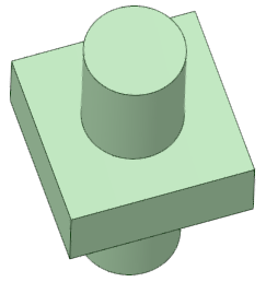
Tesselating this scene into triangle meshes will result in something like:
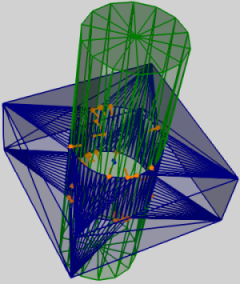
This indicates that there will be collision between the cylinder and the hole, leading to jamming if the cylinder is about to be rotated (orange vectors indicate contacts). In cases like this one, one has several options:
increasing the tesselation (details see below). This can lead to reduction of the tesselation effects, but might lead to slightly longer time needed for simulating.
increasing the geometrical gap. For instance, design models often tend to be modelled with a too small margin between geometry compared to the final models used in production. Increasing the gap helps in this case both with simulation and production.
using a joint (Joints). This will by default disable the collision between the two objects, leading to a working mechanism, and the Joint can replace the effect of the contacts.
By changing the tesselation properties, the number of triangles can be controlled. By default the rendering tesselation is used for collision detection. This means that the current settings for rendering quality (which can be different between different computers and SpaceClaim versions) determines how detailed the meshes are.
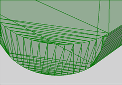
Fig. 1.1 Using Rendering Tesselation (default)
Fig. 1.2 and Fig. 1.3 show two meshes using custom setting for tesselation:
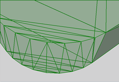
Fig. 1.2 Angle Deviation = 15 degrees .
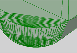
Fig. 1.3 Angle Deviation = 10 degrees.
1.8. Initial State
The initial state of a simulation is defined by the following properties:
The underlying CAD model in the document. I.e. solids, components, material properties.
The tessellation properties of the CAD geometries.
The moving parts (rigid bodies) and their transformations, mass properties and initial velocities.
The joint configurations and the joints’ initial properties.
Material settings.
Simulation settings, such as time step.
To achieve stable simulations, the initial state must be valid. See more in Valid Initial States.
1.9. Stable Simulations
See Stable Simulations for more information.