35. Granular Contact Model
Note
Feature requires a Momentum Granular license.
35.1. Introduction
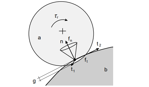
The granular bodies are represented as spheres with 6 degrees of freedom (6-DOF) with Hertzian contacts elasticity laws, Coulomb friction and rolling resistance. A contact situation is illustrated in Fig 1. Contact forces and velocities can be decomposed in the directions of the contact normals \(\pmb{\vec{n}}\) and tangents \(\pmb{\vec{t}}\). The gap function \(g(\pmb{x})\) measures the magnitude of the overlap between the contacting bodies. AGX Granular is based on a nonsmooth dynamics formulation of the discrete element method (DEM), which is reviewed below.

Figure 1: Illustration of a contact between two bodies \(a\) and \(b\) giving rise to a normal force \(f_n\), tangential force \(f_t\) and rolling resistance \(\tau_r\). The contact overlap is denoted by \(g\), the unit normal \(n\) and tangents \(t_1\) and \(t_2\).
35.2. The Smooth Discrete Element Method
In the conventional discrete element method (DEM), the normal contact force is a function of the magnitude of the overlap and its rate of change. One common function is the nonlinear Hertzian model that follows from the theory of linear viscoelastic materials. Friction is usually modeled as a spring in the tangential direction. The tangential spring extension is computed by integrating the slide velocity, and the force is projected onto the friction cone to obey the Coulomb law. Similarly, rolling resistance is modeled as torque that counteracts relative rolling motion, also limited by a Coulomb-like law. For spherical particles, the contact forces are given below:
where \(\pmb{\vec{u}}_t\) and \(\pmb{\vec{w}}_t\) are the tangential relative velocity and relative angular velocity at the contact point. The normal stiffness and damping coefficients are \(k_n = E \sqrt{2d} / 3 ( 1 - \nu^2)\) where E is the Young’s modulus, \(\nu\) is the Poisson ratio, \(d = (d_{[a]}^{-1} + d_{[b]}^{-1})^{-1}\) is the effective diameter, the dissipation coefficient is \(c = 4(1 - \nu^2)(1 - 2 \nu)\rho/15 E \nu^2\) and the material viscosity constant is \(\rho\). The friction stiffness coefficient, \(k_t\), and rolling resistance stiffness, \(k_r\), are not related to fundamental material parameters, and have to be determined by parameter tuning from experiments. Explicit time-integration is normally employed. For the sake of numerical stability the time-step must be set sufficiently small, less than \(\pi\sqrt{m/k}\). At this time-resolution the trajectories appear smooth, and therefore we refer to this method as smooth DEM.
35.3. The Nonsmooth Discrete Element Method
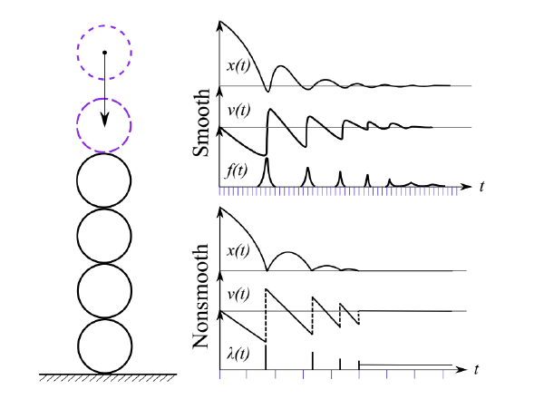
Momentum Granular uses a non-smooth discrete element method (NDEM) with the conventional viscoelastic material parameters in DEM mapped to the constraint compliance and damping parameters in the SPOOK stepper. This can be understood as an time-implicit version of the smooth formulation [2]. In the nonsmooth DEM, impacts and frictional stick-slip transitions are considered as instantaneous events that make the velocities discontinuous in time. The contact forces and impulses are modeled in terms of kinematic constraints and complementarity conditions between force and velocity, e.g., by the Signorini-Coulomb law for unilateral non-penetration and dry friction. The contact network becomes strongly coupled and any dynamic event may propagate through the entire system instantaneously. The benefit of nonsmooth DEM is that it allows integration with much larger simulation step-size than for smooth DEM and thus potentially faster.

The constraint compliance potential and dissipation function, given the constraint violation function \(g(\pmb{x})\) in a contact, is described as follows:
The regularization parameters are mapped to the Hertz contact law by:
The exponent is set to \(e_H = 5/4\) for the non-linear Hertz model with stiffness and damping parametrized as in (35.1). This connects the regularization parameters \(\epsilon_n\) and \(\gamma_n\) which can then be computed in terms of the Hertz spring coefficient \(k_n\) and the conventional material parameters as described in The Hertz Law Section.
The constrained equations of motion, based on the Hertzian contact law (35.1) become:
where \(\pmb{x}\), \(\pmb{v}\) and \(\pmb{f}_{ext}\) are global vectors of position, velocity and external force, and \(\pmb{M}\) is the system mass matrix. The explicit contact forces in (35.1) are thus replaced with non-penetration constraint forces \(\pmb{G}_n^T \lambda_n\) with Lagrange multiplier \(\pmb{\lambda}_n\) and Jacobian matrix \(\pmb{G}_n\). In (35.4), the term \(\epsilon_n \pmb{\lambda_n}\) is what brings elasticity, and \(\gamma_n \pmb{G_n} \pmb{v}\) is the viscous damping term.
When Coulomb friction and rolling resistance are also included, (35.4) is extended into to the following equations of motion:
\(\pmb{G}_t\) and \(\pmb{G}_r\) are the Jacobians of the friction and rolling resistance in the contact tangent plane. \(\pmb{G}_t \pmb{\lambda}_t\) and \(\pmb{G}_r \pmb{\lambda}_r\) are the resulting friction and rolling resistance forces in the contact. The frictional constraint imposes a zero tangential contact velocity \(\pmb{G}_t \pmb{v} = 0\), unless the tangent force reaches the frictional bounds set in the Coulomb law. The rolling resistance constraint imposes a zero rotational contact velocity \(\pmb{G}_r \pmb{v} = 0\) up to the maximum torque according to the bounds set in the rolling resistance law given by coefficient \(\mu_r\) and and effective contact radius \(r=d/2\).
When impacts occur, the equations of motion are augmented by the Newton Impact law:
for the impacting contacts and \(G v^+ = 0\) for all other constraints for the transition from impacting velocities \(v^-\) to resulting velocities \(v^+\) and \(e\) is the restitution coefficient.
The SPOOK stepper [1] is used for numerical integration of (35.5), which results in solving a mixed linear complementary problem (MLCP) of the following form:
where
and \(\pmb{l}\) and \(\pmb{u}\) are temporary slack variables used internally by the solver. The regularization and stabilization coefficients are:
The parameter \(\tau_n\) controls the dissipation rate in the normal contact force and is set according to the Contact Damping section below. The regularization parameters in (35.9) are adjusted according to the viscoelastic material properties of the contact material.
The solve stage includes two sub-stages:
The Impact Stage, where the impact equations are solved in the contacts according to (35.6). The impact forces are propagated instantaneously in the contact network by solving the impact equations in the contact network.
The Continuous Stage is when the system is time-integrated with the continuous contact equations according to (35.8) with regularization parameters in (35.3) used according to material parameters.
Both the Impact Stage and the Continuous Stage use a Parallel Projected Gauss-Seidel Solver for solving the MLCP (35.7). (Parallel or Serial is a user setting, see Granular Settings).
35.4. Summary of Parameters
This section explains the different model parameters that can be set in the MaterialPairs interface and how NDEM model uses those parameters to solve the physical system.
35.4.1. Young’s Modulus
The Young’s Modulus (\(E\)) determines the stiffness in the contact according to the following expression:
where \(\nu\) is the Poisson ratio, and \(d\) is the effective diameter. \(k_n\) is the resulting stiffness in the contact according to the Hertz law and (35.3).
Attention
The current value of Poisson’s ratio is set to 0.3 in the software. This cannot be changed by the user at this moment.
35.4.2. Friction
The frictional force \(\pmb{F}_t\) in the contact tangent plane (\(\pmb{\vec{t}}_1 , \pmb{\vec{t}}_2\)) obery the Coulomb law (35.5). This is given by the following expression:
\(| F_t | \leq \mu | F_n |\)
Where \(\pmb{F}_n\) is the friction force in the contact plane and \(\mu\) is the friction parameter given in Material Pairs interface.
35.4.3. Restitution
The restitution coefficient, \(e\), of a material determines the outgoing reflected velocity in an impacting contact according to (35.6):
Impact occur when the contact velocity exceeds a given threshold \(v_{impact}\). The threshold is automatically calculated in the software via the following formula:
where \(\epsilon\) is given by an error tolerance of \(\textbf{~2%}\), \(h\) is the simulation time step and the \(d_{avg}\) is the characteristic diameter of the active particle models in the simulation, which is defined as the average diameter. The characteristic diameter can be adjusted manually under Granular Settings.
35.4.4. Rolling and Twisting Resistance
The Rolling Resistance give rise to a torque \(\pmb{\tau}_r\), acting in the contact tangent plane. The magnitude of the resistance torque is limited by a Coulomb like law.
\(| \tau_r | \leq \mu_r r | F_n |\)
Where \(\pmb{\tau}_r\) is the generated rolling resistance force in the rotational directions along the tangent plane, \(\mu_r\) is the rolling resistance coefficient and \(r\) is the effective radius \(r = d / 2\).
The same formula applies for the twisting resistance, expect that the resistance torque applies on rotational motion around the normal direction (\(\pmb{\vec{n}}\)).
Attention
When using granular flows consisting of Rigid Bodies the rolling resistance part of the contact equations are omitted; The resistance is instead modelled via the shape irregularity.
35.4.5. Contact Damping
The damping at high-velocity impacts is controlled by the restitution coefficient. For continuous contacts the dissipation rate in the contact normal direction is controlled by the damping parameter in (35.9). By default the damping parameter is automatically calculated:
where \(n_s = 4.5\) and \(h\) is the simulation time step, which is set to ensure stable simulations irrespective of time steps. This can be replaced by a physically based dissipation model if the time-step \(h\) is decreased to the smooth regime. The general guideline for choosing the damping parameter is given by the following equation:
where \(\gamma_n^{-1} = k_n c / e_H^2\)
and $k_n$ and $c$ are the stiffness and dissipation coefficients as in Hertz section. Manual input for the damping time can be given per material in Material Pairs.
35.4.6. Contact Adhesion
Adhesion defines an attractive force that can simulate stickiness. It operates only on bodies that have colliding geometries, i.e. it is not a general force field.
Adhesion This option specifies a force magnitude, that is the upper bound of the attractive force acting between two colliding bodies in the normal direction.
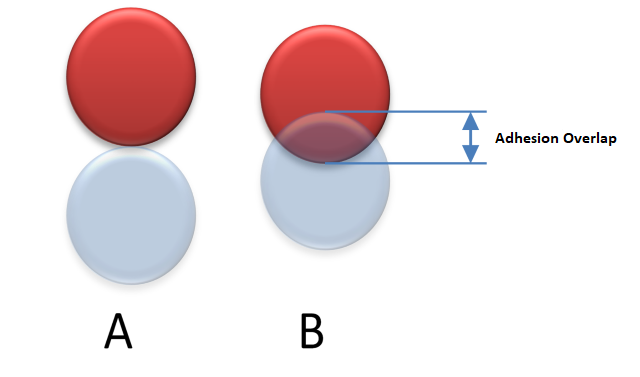
Adhesive Overlap When the contact overlap exceeds the Adhesive Overlap the force become repulsive according the normal Hertz model. The adhesive force acts only when the contact overlap is less than the Adhesive Overlap and vanishes when there is no overlap. It is important to specify a finite and positive Adhesive Overlap to ensure there is a contact regime where adhesion can occur.
Attention
The adhesive force arise in the non-penetration constraint by subtracting the contact depth with the Adhesive Overlap to produce negative depth and a positive force. The bounds of the constaint are changed to allow for such non-positive contact foces in the overlap region according to the limit of the Adhesion value.
The adhesion distance will change the depth of the resting contact as seen in the image below.

Figure 2: By default the Adhesive Overlap is zero and a repulsive contact force arise when two particles overlap (A). When adhesion is activated the contact force switch from adhesive to repulsive when the overlap exceeds the Adhesive Overlap.
35.5. Simulation Parameters
The key simulation parameters that have to be adjusted to properly configure a simulation with granular materials are listed in this section.
35.5.1. Resting iterations
The Parallel Projected Gauss Seidel (PPGS) algorithm is a fixed-point iteration scheme for computing the contact forces and corresponding velocity updates in (35.8). The number of resting iterations parameter determines the number of times each contact equation is solved during a time-step. High number of iterations yields a more precise solution but reduces the computational performance. When the number of iterations are small, numerical errors can be observed as artificial elasticity (large contact overlaps) and insufficient friction. The required number of iterations depend on size of the contact network in the direction of dominant force. For guidelines on setting suitable number of iterations, see reference [2]. More information about iterative solvers can be found in the Granular Settings section.
35.5.2. Impact Iterations
The impact stage propagates the impact impulses instantaneously in the contact system according to (35.6). This creates a number of equations that is solved by the PPGS solver. The number of impact iterations determines how many iterations that should be used when propagating the impulses in the system. The higher number the better solution for the impact propagation.
Control the number of impact iterations via the Granular Settings.
35.5.3. Warm Starting
The PPGS solver can be warm-started by using the constraint multiplier lambda ( \(\lambda\) ) from the solution of the contact constraint equations in the previous time-step. In general, this will enable contacts that persists over time to converge faster and result in a more precise solution of PPGS solver with fewer number of iterations. This option is recommended when simulating slowly evolving systems with contact networks. For rapidly evolving systems, there is little benefit from using warmstarting or even risk that it worsen the convergence.
Enabling solver warm starting can be done via the Granular Settings.
35.6. Parallel Projected Gauss Seidel (PPGS)
The mixed linear complementarity problem resulting from the contact system SPOOK (35.8) is solved in Algoryx Momentum by a Parallel-Projected Gauss-Seidel Solver (PPGS). More information about iterative solvers are given in section Stable Simulations. The solver first partitions the system into different subdomains and interaction zones that are solved in parallel via multithreading. The solution from the parallel solver is equivalent to running it in serial. Options for setting the number of resting and impact iterations is given in Granular Settings. The iteration count used in the solver can be adjusted according to fidelity needs.
35.7. Choosing time-step and solver iterations
The solver settings needs to be configured according to the system size in the scene if the goal is to reach high fidelity in the granular simulations. This involves two important steps:
Setting the correct time-step. Dependent mainly on system velocities to prevent tunneling effect but can also affect solver results.
Setting the correct iteration count for the particle solver. Higher iteration counts will generally yield more accurate solutions.
There are currently two types of iteration settings that covers different distinct phenomena captured by separate stages in the solver:
1. Resting Iterations. These govern the solver fidelity with regards to resting contacts with lower velocities. This is important to change if your system has relativley low velocities and are often in stationary conditions such as soil and pile formation, where impacts are not important to resolve.
2. Impact Iterations. These govern solver fidelity in the impact stage where impulses are propagated in the system according to Newton’s impact law. Increase this if the system is highly dynamic and dominated by impacts that needs to be resolved accuratley in order to capture the desired effects.
There is a trade-off with respect to compute performance and solver fidelity. Early on in the design process you might use lower iteration counts to get rough estimates at a relative fast pace while later on when higher fidelity is required the iteration count is increased, which also increases the required compute time. The following is a paraphrased excerpt from appendix A1 in [3] that provides guidelines for how to set the iteration count to achieve good fidelity for a specific system size and contact configuration.
A recommended guideline is provided for setting the time step for a given error tolerance \(\epsilon_n\) in a NDEM simulation [4]:
where \(d\) is the particle diameter, \(v_n\) is the normal contact velocity and \(\dot{v}_n\) is the largest potential acceleration that can occur from the forces acting on a particle. In a dense packing the potential acceleration can be estimated by \(\dot{v}_n \approx \sigma A_p / m_p\) , with particle cross-section \(A_p = \pi d^2 / 4\), mass \(m_p\) and the characteristic stress \(\sigma\) that may be estimated from known external loads. In the absence of external loads, the potential acceleration coincides with the gravity acceleration.
The number of projected Gauss–Seidel iterations has been found to satisfy the following relation [4]:
where \(n\) is the length of the contact network (number of particles) in the direction of the dominant stress.
Two examples are considered next. Assume and error tolerance of \(\epsilon = 0.01\) and consider a quasi-static system ( \(v_n \approx 0\) ) with smallest particle diameter \(d_p= 0.01 m\) and mass \(m_p = 0.001 kg\) confined in a cubic container with side length \(L= 0.1 m\) and wall pressure \(\sigma\). For a pressure of \(\sigma=1.0 kPa\) the acceleration become \(a=78 m/s^2\) and the time-step limits \(\Delta t \lesssim 1 ms\). For the larger pressure \(\sigma=100 kPa\) we get \(a=7800 m/s^2\) and \(\Delta t \lesssim 0.1 ms\). Since the side-length is \(n \sim 100\) particle diameters, the number of iterations become \(N_{it} \gtrsim 1000\).
References