12. Edit

In the Edit section of the Ribbon menu you can find the Split and Merge buttons. They are used to organize your model to be suited for simulation by splitting and merging components into individually moving parts, rigid bodies.
Dynamics Color help you understanding how your model is split into rigid bodies.
Algoryx Momentum is designed with the idea that your CAD model should be treated as read-only, meaning that if your CAD model is organized in such a way that individual parts belong to separate sub-trees/components, it will be very simple to also organize the simulation structure into rigid bodies. Still, you might want to reduce the complexity of the model by disabling/removing unwanted geometry such as holes etc., which does not contribute to the simulation. Sometimes you also need to re-organize the CAD model to make it suitable for simulation. For example if individually moving parts are modeled as one solid, you need to split your CAD model into separate components.
The first time you open an existing model, all components will be merged into one single rigid body. This will basically create a simulation in one rigid body falling in gravity, that is your first iteration of the simulation. From this you can split the simulation model into moving parts.
12.1. Split
Splitting can be done on one or more rigid bodies or components. When splitting a rigid body, a new rigid body will be created for each Component in the original rigid body. Selecting which components to split can be done by selecting a face, edge, solid or component for each object you want to split from the current rigid body.
If you want to break out one or more components into one new rigid body you can select one or more components in the rigid body, press split, and you will get one new rigid body for each selected component. Fig. 12.1 show a scene with four components, all merged into one rigid body “RigidBody2”:

Fig. 12.1 Simulation structure before we split Component1 and Component4.
If we select Component1 and Component4 and choose to split we get a new simulation structure:

Fig. 12.2 Result after splitting the two components.
Now we see that the two selected components each belong to a new rigid body. They are still selected, so if you choose Merge in the right mouse menu, they will be merged into one single rigid body.
If you want to explode your model into one rigid body for each component, you can select the rigid body and press split. This would result in a model with one rigid body for each component.
Attention
After a split operation: Any attributes for the split rigid body such as velocity, mass, name etc. will be discarded.
12.2. Merge
There are several ways of merging components into a common rigid body:
Drag and drop of bodies/components in the Simulation Structure.
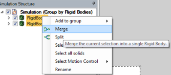
Selecting bodies and components and use the right mouse menu button in the Simulation Structure.
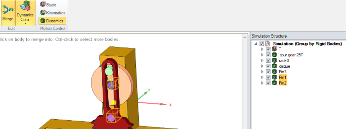
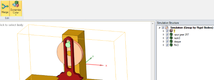
Using the Merge tool from the Edit menu.
When two rigid bodies or components are merged into one rigid body, they will move together as one. This can be used to reduce the number of moving rigid bodies in a simulation.
12.2.1. Drag and drop
By selecting components or rigid bodies in the simulation structure (the source), and then dragging and dropping those onto another rigid body (the target), the target rigid body will be retained and augmented with the components from the source.
12.3. Dynamics Color
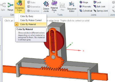
Dynamics Color can help you understanding the structure of your model. By coloring solids depending on their partnership of rigid bodies, motion control, by material, by collision shape, or by complexity of the volume mesh, you quickly get a picture of how your model is constructed.
12.3.1. Color By Body
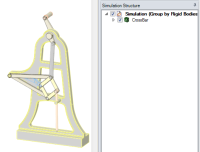
Color by Body will assign a unique color for each rigid body of your construction and thus give you an understanding of the mechanical structure of your simulation model. Starting with a model containing one rigid body, Color by Body will draw the entire model using one color:
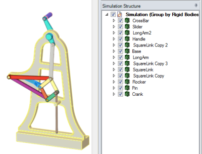
If the model is split into separate moving parts/rigid bodies, Color By Body will for each moving part use a separate color:
12.3.2. Color by MotionControl
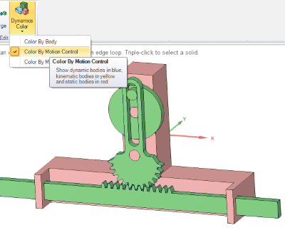
With this mode, each rigid body will be assigned a color based on its motion control.
12.3.4. Color By Collision Shape
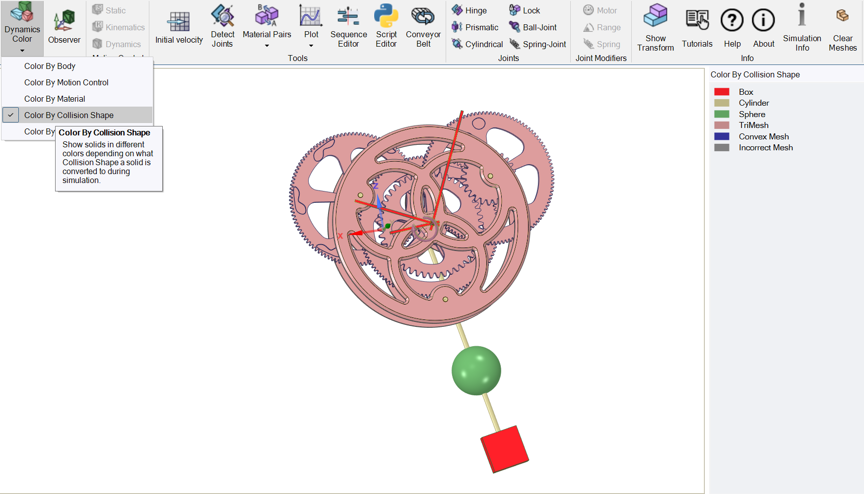
This mode assigns a color to each geometry based on the type of Collision Shape it represents in the simulation, see Primitive Identification. Momentum’s collision algorithm is more efficient in handling collisions between simple primitives than using e.g. triangle meshes. There are five different types of collision shapes in Momentum, see the table Collision Shapes. The representation of Geometries in Momentum..
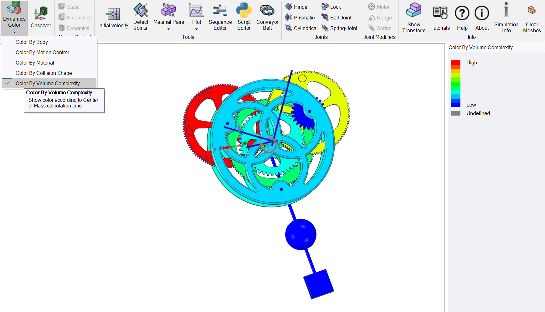
12.3.5. Color By Volume Complexity
This mode assigns a color to each geometry based on the amount of time SpaceClaim takes to calculate its mass properties, such as volume and center of mass. This measurement, referred to as “Volume Complexity,” roughly indicates the level of complexity of the geometry mesh. The most complex geometries are displayed in red, while the least complex are blue. Solids with complex meshes require more time to compute their center of mass, volume, and mass, and also pose greater challenges in collision handling within Momentum. With this color mode, users can quickly assess which solids in SpaceClaim are complex to modify and which ones may be computationally intensive in Momentum’s collision handling. Note that the coloring is just an estimate based on calculation time, which may vary due to machine load and other factors, and is not a true complexity measurement.
All geometries that have no mass or if the mass isn’t calculated for that geometry are colored gray.
Attention
Dynamics Color will be temporarily disabled during recording of a simulation.
Attention
If Passive Mode is activated the coloring of components is disabled regardless of whether the coloring is enabled or not.

