38.2. RigidBody Properties
A rigid body is a dynamic body with 6 degrees of freedom which carries mass and inertia. It can contain one or more Components which in turn contains one or more Solids, representing the geometry/shape of the rigid body.
A rigid body can be associated with joints which will restrict the motion of the rigid body.
An easy way to access a rigid body and its properties is via the Simulation Structure.
38.2.1. Properties

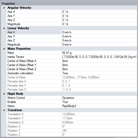
Angular Velocity: The initial angular velocity for the rigid body. Given in world coordinate system.
Linear Velocity: The initial linear velocity for the rigid body. Given in world coordinate system.
38.2.1.1. Mass Properties
Mass: The mass of the rigid body. By default, this mass is automatically calculated based on the volume of all solids belonging to components for this rigid body and the density, as specified by the SpaceClaim material. See Material Pairs. If the mass is manually changed, it will no longer be automatically calculated by SpaceClaim.
Inertia tensor: The inertia specifies the resistance to change in angular velocity about an axis of rotation. By default it is calculated from the density and the volume of the solids associated to the rigid body, analogous to the mass.
Center of Mass Offset X,Y,Z: Specifies an offset of the automatically calculated center of mass.
Automatic calculation: If true, the mass, inertia tensor and center of mass will be automatically calculated.
Center of Mass X,Y,Z: The calculated center of mass for the rigid body.
Principal Axis X,Y,Z: The coordinate system, in which the Inertia tensor is defined.
38.2.1.2. Setting Inertia via Python
The coordinate system which inertia tensor is defined in is the principal axis, using the center of mass as the origin point. If this frame does not match the frame which the input inertia has been taken from, there are functions to help with this in the Python API.
This is done by placing an Observer, with its origin in the target center of mass of the rigid body. The frame of the Observer is the coordinate system which the input inertia tensor should be defined in. It will be converted to match the principal axis defined by SpaceClaim.
sim = v1.getSimulation()
rb  = sim.getRigidBody('RigidBody')
obs = sim.getObserver('Observer')
inertia = v1.Matrix3x3( ... )

rb.setCmAndInertiaInObserver(obs, inertia)
38.2.1.3. Valid inertias
The inertia tensor is a 3 by 3 matrix with several constraints on it. The inertia tensor must follow each of these constraints to be set, otherwise an error will be returned.
Given that the matrix is defined follows:
The following constraints are put on it.
The matrix is symmetrical over the A, E, I diagonal. This means that the following elements needs to be the same:
Beyond this, the matrix must be positive definitive. That means that the determinants of A, the matrix ABDE and the entire matrix must be positive. The following equations must then be true:
If all these equations are true, then the inertia tensor can be used for Algoryx Momentum.
38.2.1.4. Rigid Body
Motion control: Specifies how the rigid body will be simulated. See Motion Control
Enable: Specifies if the rigid body is part of the simulation or not.
Name: The name of the rigid body.
38.2.1.5. Transform
Read-only values. Translation X,Y,Z: Display the current position of the rigid body. Rotation X,Y,Z: Display the current orientation of the rigid body.
The transform of the rigid body will be calculated as the delta rotation from the principal axes of the rigid body and the parent component transformations.