38.1. Geometry/Solid Properties
A Geometry is used to define the spatial representation of a rigid body. It can collide with other geometries which create contact joints for restoring the non-penetrating state. Each Solid in SpaceClaim is converted into a representing a geometry in Algoryx Momentum.
38.1.1. Properties
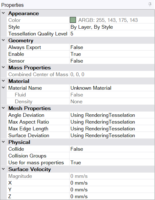
38.1.1.1. Geometry properties
Always Export Used when exporting to agx files. This option specifies if the geometry always should be exported to agx-files even if it is hidden and the Add-In Option Do not export hidden geometries with collide set to false is enabled.
Enable: Specifies if this solid will be part of the simulation or not. If disabled, the solid will no longer follow the parent component/rigid body. It will not be exported for rendering either.
Sensor: For future use. Specifies if the geometry is a sensor.
38.1.1.2. Material
Material Name: Specifies the SpaceClaim material used for this solid. This material will be used for specifying Material Pairs settings and density.
38.1.1.3. Mesh/Tesselation Properties
With these properties, the tesselation of a specific solid can be controlled, see also “Use rendering tesselation” here Use rendering tesselation. To see the tesselation used in the simulation, you have to open the Simulation View.
Attention
Be careful when changing the default tesselation settings as they can result in a large number of triangles. Something that will have a substantial negative effect on performance.
Angle Deviation: Sets the maximum angle of the surface normal of two adjacent faces. A higher value will increase the density of faces of the mesh in areas of high curvature, and will decrease the density in flatter areas.
Max Aspect Ratio: Sets the maximum aspect ratio (height/width) of new mesh faces.
0 - Ignores the aspect ratio limitation.
1 - Specifies that the height and width must be the same.
Greater than 1. Sets the maximum ratio by which the height can exceed the width.
Greater than 0 but less than 1. Sets the maximum ratio by which the width can exceed the height.
Max Edge Length: Maximum length of an edge of a new face.
Surface Deviation: Sets the maximum deviation of the mesh faces from the surface or shape of the original object. Smaller values result in less deviation, but create more faces.
38.1.1.4. Physical
Collide: Specifies if the geometry will collide with other geometries or not.
Use for mass properties: Specifies if the solid/geometry should be part of the mass calculation for the rigid body or not.
38.1.1.4.1. Collision Groups
Collision Groups is a concept that allow you to disable collision detection between Solids. The workflow is the following:
Select one or more solids that you want to assign to one or more Collision Group(s).
Select an existing or Create a new Collision Group and press Add to assign the Group to the selected solid(s).
Repeat 1-2 until you are done assigning Collision Groups to the selected solids(s).
Press the Disable Collision Pairs tab in the Collision Group UI.
Select two Collision Groups that you want to disable and press Create Pair.
Repeat 5 until you have created the desired Disable Collision Pairs.
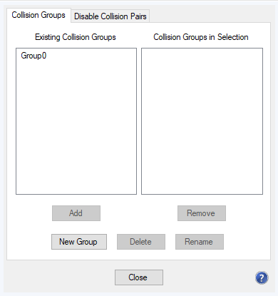
Fig. 38.1 Collision Group UI for adding and removing Collision Groups to the document and the selected Solid(s).
The left list in Fig. 38.1 list the available Collision Groups in the document (that is not already assigned to the current selection of Solids). To the right, the Collision Groups for the currently selected solids are listed. A Group with an asterix (*) indicates that some but not all of the solids belongs to this Collision Group.
This UI allow you to add/remove and rename Collision Groups in the document:
To add a new Collision Group to the document, press New Group.
To remove a selected Collision Group from the document, press Delete.
To rename a selected Collision, press Rename or F2 and enter the new name.
You can also assign or remove Collision Groups from the currently selected solids:
To assign a Collision Group to the currently selected solids: in the left list, select a Collision Group and press Add.
To remove a Collision Group from the currently selected solids: in the right list, select a Collision Group and press Remove.
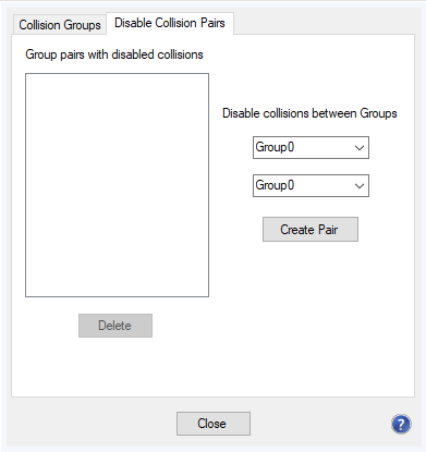
Fig. 38.2 Collision Group UI for adding and removing Disable Collision Pairs.
Fig. 38.2 show the UI for adding and removing Disable Collision Pairs. Here you can add or remove pairs of Collision Group which should be disabled for collision detection. See Fig. 38.4 below for an example.
To create a new Disable Collision Pair: Select the two groups in the drop down menu and press Create Pair. The two groups in the pair will now be disabled for collision detection.
To remove a selected Disable Collision Pair: Press Delete.
In Fig. 38.3 we have a scenario where the selected cylinder (Wheel) is currently colliding with the box (Chassie). Assume also that we would like to turn the wheel using the hinge attached to the chassie. At the same time, we want the wheel to collide with the ground so we cannot just disable Collision detection for the Wheel using the Collide property. This can be achieved using collision groups.
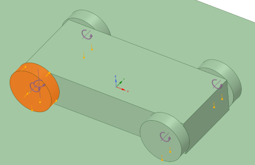
Fig. 38.3 A scene where we would like to be able to turn (horizontally) the wheel without colliding with the chassie.
Select the solids of the four wheels.
Choose the Collision Groups in the Property window.
Add a new Collision Group by pressing New Group.
Name the group: Wheel.
Select the chassie (box) and create another Collision Group named: Chassie.
In the Collision Group UI, select the Disable Collision Pair tab.
Select Wheel and Chassie in the drop down menu and press Create Pair.
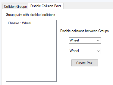
Fig. 38.4 The Collision Pair consisting of Wheel and Chassie will now disable collision detection between these two groups.
Fig. 38.5 show that the Wheel can freely rotate without colliding with the box.
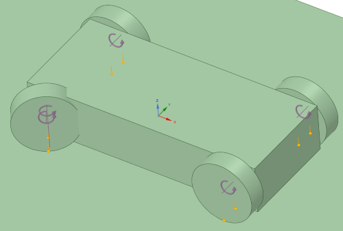
Fig. 38.5 Now the wheel is free to rotate without collision with the chassie.
38.1.1.5. Surface Velocity
X,Y,Z: Surface velocity in the three axes in local coordinate system of the parent component).
Specifies a velocity in the local coordinate system (of the parent component) for the surface of the solid (will be rotated with the parent Component). This velocity can be used to emulate a conveyor belt.