23.1. Hinge Joint
The Hinge joint ( ) removes all but one DOF (degree of freedom leaving the affected rigid body only able to rotate around the selected axis.
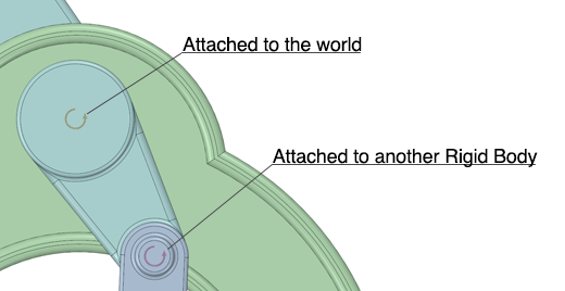
As with all the joints, there are two ways of attaching the Hinge joint:
Attach it directly to an edge or an axis of a solid belonging to a Rigid Body, which attaches the joint between the Rigid Body and the world.
Attach it between two separate solids (each belonging to a separate Rigid Body).
23.1.1. Usage
In the first case you simply select the hinge tool from the ribbon menu and left-click on an edge or an axis of the Rigid Body you wish to add a joint to, a yellow Hinge icon will appear on the edge or axis. See Joint status.
In the second case where you wish to join two Rigid Bodies with a hinge joint you simply select the Hinge joint from the ribbon menu. Then, Ctrl-click somewhere on one of the Rigid Bodies, and then click the edge or axis on the other Rigid Body that the hinge should rotate around. A purple Hinge icon will appear on the edge or axis. See Joint status.

23.1.2. Properties
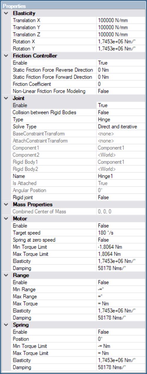
When one hinge (or multiple hinges) is selected the properties of that hinge can be changed from the properties tab.

23.1.2.1. Joint Properties
The properties specifies the initial state for a joint.
Enable: Specifies whether the joint is enabled or not.
Collision between Rigid Bodies: Specifies if there can be contacts generated between the two attached rigid bodies. Default is off. If collision is enabled, there might be jamming effects if the two bodies have overlapping geometry.
Type: Type of joint.
Solve type: Specifies which solver that will solve this joint.
Direct And Iterative: (Default), both the direct AND the iterative solver will see this joint. To get stable friction with the Split solver type for Material Pairs, both the iterative and the direct solver must see the joint.
Iterative - Only the iterative solver will see this joint. Will lead to instabilities for large mass ratios.
Direct - Only the direct solver will see this joint. This might lead to artifacts when involving a Material Pair with Split solve type.
Component1: Name of the first component associated to this joint.
Component2: Name of the second component associated to this joint.
Rigid Body1: Name of the first rigid body associated to this joint.
Rigid Body2: Name of the second rigid body associated to this joint.
Reverse direction: Visible only if joint is attached to two bodies. Will swap the two attached rigid bodies, effectively flip the direction of the joint.
Angular Position: The current angle of this hinge joint.
Is Attached: A property that is set to true when the joint is directly attached to an edge/axis on a solid. When the joint is created, it is always directly attached to an edge/axis on a solid. If the solid is moved, the joint will follow the solid. However, if the joint is moved individually from the solid, this property is changed to false. This means that the joint will no longer follow the solid when the solid is moved, but will remain at its current world location. To reset the joint’s world position to the original solid position, set this flag to true.
23.1.2.2. Elasticity
Elasticity specifies the “stiffness” of the remaining degrees of freedom for the joint. The elasticity is specified in a local coordinate system relative to the constraint axis.
Translation X,Y,Z: Specifies elasticity in the three translational DOF.
Rotation X,Y: Specifies elasticity in the two remaining rotational DOF.
23.1.2.3. Internal Friction
Specifies properties for the Internal Friction in the hinge around its axis. An internal friction will dissipate energy from the hinge, see Internal Friction.
Enable: Specifies whether the internal friction is enabled or not.
Static Friction Force Reverse Direction: The internal friction includes a setting for minimal static friction force, meaning there is a friction resistance even with the Coefficient of Friction set to zero. The static friction have one value for the reverse direction and one value for the forward direction.
Static Friction Force Forward Direction: The internal friction includes a setting for minimal static friction force, meaning there is a friction resistance even with the Coefficient of Friction set to zero. The static friction have one value for the reverse direction and one value for the forward direction.
Coefficient of Friction: The Coefficient of Friction. For the friction condition to be dimensionally correct, the axle radius should be included in the Coefficient of Friction, \(\tau_{friction} \leq \mu r F_{normal}\), where the given Coefficient of Friction should be \(\mu r\).
Non-Linear Friction Force Modeling: This mode is similar to direct friction for contacts and will affect the performance but will also increase the accuracy of the simulation, see Non-Linear Force Modeling.
23.1.2.4. Motor
Specifies properties for the Motor which operates on the hinge axis. A motor is an effort joint that will try to drive the hinge to a current speed that corresponds to the desired speed.
Enable: Specifies whether the the motor is enabled or not.
Speed: Specifies the desired speed of the motor. Can be specified as: 100 rpm, 2 rad/s, 100 deg/s.
Spring at zero speed: When the Speed is set to zero, this motor will act as a Spring joint, locking the hinge at its current position. Handy when simulating a gripping mechanism.
Torque Limit: Specifies the upper and lower limit for the torque that this motor can apply. Max torque is applied in the positive direction of the hinge, Min torque is applied in the negative direction of the hinge.
Elasticity: Specifies the stiffness of this motor. A larger value will result in a stiffer joint.
Damping: Specifies the spring damping coefficient for the motor.
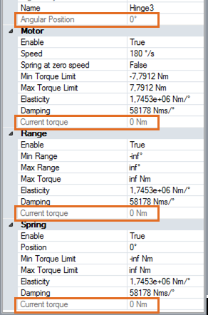
Current torque: In playback, when a recording of a simulation is done, this field will show the torque being applied by the motor.
23.1.2.5. Spring
Specifies properties for the torsional Spring which operates on the hinge axis. A spring defines a position in the range [-INF,INF] which the hinge will try to satisfy. A hinge always starts at the position 0. Rotating the two bodies around the hinge axis will increase/decrease the current position.
Enable: Specifies whether the the spring is enabled or not.
Position: Specifies the position (angle) of the spring. This defines the equilibrium state of the torsion spring. The spring will strive to satisfy this by rotating the hinge until the current position of the hinge equals the spring position.
Torque Limit: Specifies the upper and lower limit for the torque that this spring can apply. Max torque is applied in the positive direction of the hinge, Min torque is applied in the negative direction of the hinge.
Elasticity: Specifies the stiffness of this spring. A larger value will result in a stiffer joint.
Damping: Specifies the spring damping coefficient.
Current torque: In playback, when a recording of a simulation is done, this field will show the torque being applied by the spring.
23.1.2.6. Range
Specifies properties for the Range which operates on the hinge axis. The range specifies a range in which the hinge can rotate. The range can be any number of degrees in positive and negative direction. So a value of 720 means two full revolutions in positive direction.
Enable: Specifies whether the the range is enabled or not.
Min, Max range: Specifies the range in which the body/two bodies are free to rotate. If a body/bodies are forced outside this range, a maximum torque of Torque Limit will be applied.
Torque Limit: Specifies the maximum torque magnitude that this range can apply to its body/bodies.
Elasticity: Specifies the stiffness of this range. A larger value will result in a stiffer joint.
Damping: Specifies the spring damping coefficient at the range position.
Current torque: In playback, when a recording of a simulation is done, this field will show the torque being applied by the range.
23.1.2.7. Current Properties
When a simulation is being recorded or played back, some information is available as read only properties. These include current angle and and applied torque for spring, range and motor (if enabled).
